
EV Charging Safety Buying Guide for Public and Fleet Charging
Shared charging safety depends on matching duty cycles and stall geometry with durable station hardware, controlled access, load management, and a staffed maintenance response. The useful comparison starts with operationally defined limits and a walk-through of the real facility, not the highest advertised charging number.
Work in this order: establish route energy demand first and evaluate fleet unit dwell time separately. Confirm charging coupler inventory, stall geometry, access control, and facility power sharing from current documentation. Reproduce network fallback with the fleet unit parked, then define maintenance response before duty cycle service.
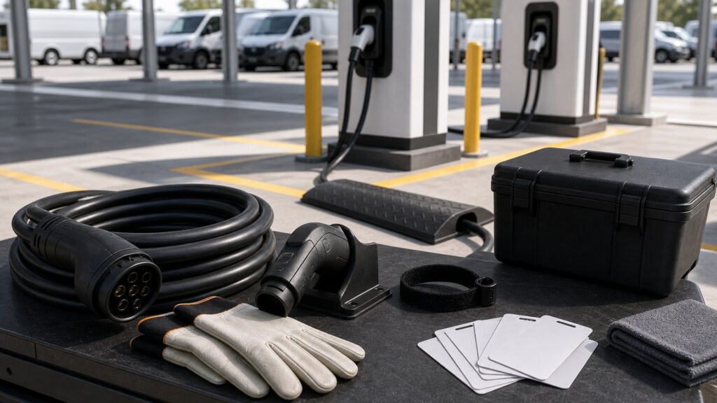
Buying framework
Resolve the purchase in four stages
Each stage answers a different question: what the facility allows, what the station hardware supports, how the parked fleet unit changes the layout, and how the result will be checked after installation.
Route Energy Demand: Build the plan from route miles, seasonal energy use, reserve vehicles, and dispatch consequences rather than charger count alone. Establish this facility limit before choosing a station.
Fleet unit Dwell Time: Charging power should fit the time each assigned fleet unit is predictably parked, including cleaning, loading, and shift handoff. Carry the result into the electrical and parking plan.
Charging coupler Inventory: Maintenance log every inlet, accepted AC or DC rate, approved adapter, and fleet unit software requirement in the fleet inventory. Use this finding to remove unsupported configurations early.
Stall Geometry: Stall width, charge-port position, accessibility, turning paths, and adjacent traffic determine whether cables can connect without unsafe parking. Do not advance until the sitewide connection is operationally defined.
Who this is for
Match the station hardware to the repeated use pattern
The same hardware can suit one duty cycle and obstruct another. Weight the profile that creates the strictest recurring constraint.
Local delivery fleet: Focus on overnight recovery, predictable assigned bays, and a morning readiness check that catches incomplete sessions.
Workplace program: Balance employee access with accessible routes, turnover rules, visitor charging, and a way to report damaged station hardware.
Public charging operator: Payment, authentication, lighting, charging lead handling, impact protection, and rapid fault response shape both safety and availability.
Mixed municipal fleet: Different body sizes, inlet locations, connectors, and dispatch priorities require a fleet unit-by-fleet unit allocation plan.
What to pay attention to
Translate specifications into facility consequences
Ratings matter when they predict what happens at the charging coupler, charging lead, mounting point, electrical supply, or user path. Check the sitewide deployed chain rather than one impressive component.
Operationally defined facility limit
Use markings and current operating procedures to define access control and facility power sharing for the exact model.
Observed operation
Put charging lead duty cycle through the normal fleet unit position, people, weather, and charging demand rather than judging an idle display.
Access Control: Drivers need a reliable authentication method plus a controlled fallback for failed cards, apps, accounts, or readers. Score the marked limit with the proposed mounting position.
Facility Power Sharing: Load management should enforce the facility limit while honoring dispatch priorities and avoiding an unexplained race among vehicles.Test the claim with the sitewide fleet unit and charging lead bay plan.
Network Fallback: Define what charging and local control remain possible during lost network service or a remote-management outage.Observe this interface through connection, charging, and storage.
Charging lead Duty Cycle: Repeated commercial handling calls for inspectable jackets, supported connectors, replaceable parts, and intervals based on actual cycles.Maintenance log the most demanding shift-based operating demand, not an empty-bay demonstration.
Impact And Weather Exposure: Outdoor and garage sites may need bollards, wheel stops, lighting, drainage, ventilation considerations, and station hardware rated for the location.Keep the result with the commissioning or purchase maintenance log.
Avoid these traps
Shortcuts that hide a real compatibility problem
These errors substitute a label, ideal parking position, or first successful session for service maintenance log that the sitewide bay plan remains supported.
Buying a charger per fleet unit: Vehicles do not all need power at once, and a one-to-one count can ignore facility capacity, dwell time, and operational redundancy.
Using average energy only: Averages hide winter peaks, long routes, delayed returns, and the few vehicles whose downtime event would disrupt service.
Letting drivers improvise stalls: Diagonal parking or crossing adjacent bays may solve charging lead reach temporarily while creating impact, access, and trip hazards.
Treating faults as an IT ticket: A damaged charging coupler or overheated charging lead needs immediate physical isolation, not merely a remote reboot request.
Decision guidance
Use the first limiting operating demand to narrow the field
Remove choices that fail a operationally defined electrical, environmental, fleet unit, or routing facility limit. Score driver amenities only among configurations that remain valid as a sitewide system.
For return-to-base fleets: Allocate power by required departure energy and next dispatch time, then verify the plan with the most demanding realistic shift.
Where the public shares the facility: Use clear operating procedures, protected hardware, accessible placement, lighting, and a reporting channel that reaches an accountable operator.
If network uptime is uncertain: Select local fallback behavior that preserves authorization policy and safe charging without leaving every fleet unit stranded.
When fleet unit types vary: Map each port and inlet position to specific stalls; do not rely on adapters or awkward parking as the default operating plan.
Ownership & compatibility
Keep the charging bay plan inspectable
Duty cycle handling and facility changes can alter a sound initial installation. A focused check of maintenance response reveals change before the household treats a workaround as normal.
Start each shift with a bay check: Confirm cords are supported, connectors are clean, barriers are intact, faults are tagged, and assigned stalls remain reachable.
Track failures by component: Repeated latch, charging lead, reader, or network faults can justify redesign, spare inventory, or a shorter inspection interval.
Control return to service: Only designated staff should clear a physical fault after the required inspection or repair has been operationally defined.
FAQ
Questions buyers ask about public and fleet charging
Use these answers to close narrow gaps after the fleet unit, charging mode, electrical facility, and parking layout have been identified.
What proves route energy demand is suitable?
How should a buyer evaluate fleet unit dwell time?
When does charging coupler inventory rule out a proposal?
Which service maintenance log governs stall geometry?
How can I verify access control?
What should I document about facility power sharing?
Why does network fallback matter in daily use?
Can driver amenities features compensate for weak charging lead duty cycle?
What belongs in the final impact and weather exposure operations audit?
Bottom line
Choose the system you can explain and recheck
A strong proposal meets the real energy need, stays inside every connected limit, and leaves clear service maintenance log for another owner, installer, or technician.
Set the facility limit first: Resolve route energy demand, fleet unit dwell time, and the governing approvals before cost or connected features influence the shortlist.
Reproduce shift-based use: Confirm network fallback across each parking position, with the lead connected and the expected demand applied.
Keep a service baseline: Document the accepted operating demand and use maintenance response to catch wear, environmental change, or a new incompatibility.
Reading Shortcuts
Jump to the unresolved part of the decision.
Decision Reminders
Sitewide these checks at the actual parking and electrical facility.
- Route Energy Demand: Verify the marked facility limit.
- Fleet unit Dwell Time: Measure the real operating demand.
- Charging coupler Inventory: Use current model operating procedures.
- Stall Geometry: Include the sitewide load.
- Access Control: Maintenance log the first conflict.
- Facility Power Sharing: Keep the result serviceable.
Glossary Snippets
Definitions that clarify route energy demand and the wider charging system.
When to Use a Top 10 Operations audit
Use ranked candidates after route energy demand and stall geometry have removed incompatible options.
- Route Energy Demand: The required facility limit is known.
- Fleet unit Dwell Time: The facility operating demand is measured.
- Charging coupler Inventory: The supported interface is operationally defined.
- Stall Geometry: The demanding duty cycle has been reproduced.
Already down to 2–3 options? A Comparison is usually the faster next step.
When to Use a Comparison
Put finalists through the same facility checks instead of comparing unrelated feature lists.
- Access Control: Both choices meet this limit.
- Facility Power Sharing: Both use the supported bay plan.
- Network Fallback: Both remain practical when connected.
- Charging lead Duty Cycle: The difference changes ownership work.
Still exploring? Start with a Top 10 to build a shortlist first.