
How to Choose Car Electronics & Driving Tech for Installation and Wiring Requirements
Automotive electronics live in a harsh electrical and physical environment: voltage changes, vibration, heat, moisture, sharp sheet metal, moving trim, airbags, and long parked periods. A device can power on during installation yet create voltage drop, noise, battery drain, overheated wiring, water entry, or unsafe deployment interference months later.
This guide plans the circuit before buying installation parts. It covers continuous and startup current, wire gauge and length, fuses, relays, grounds, ignition sensing, vehicle sleep, connectors, grommets, abrasion and strain relief, trim routing, testing, service access, and documentation. High-voltage, restraint, security, and networked systems remain professional territory when approved procedures and equipment are unavailable.
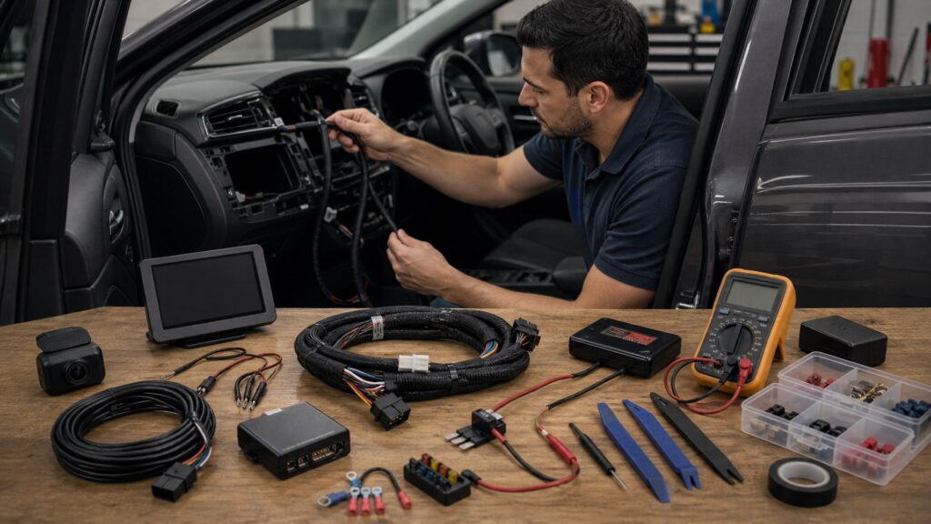
Buying framework
Design the circuit before choosing the wire
Start with the device load and operating modes, then select the source, protection, conductor, return path, routing, and acceptance measurements.
Document every operating mode: Record supply voltage, continuous and peak current, startup surge, parking mode, low-voltage cutoff, memory draw, shutdown delay, and simultaneous accessories. Marketing wattage is not a complete load profile.
Choose a verified power source: Use vehicle information and measurements to identify constant, switched, delayed-accessory, or dedicated battery supply. Confirm circuit purpose, capacity, shutdown behavior, and consequences of a shared fuse.
Engineer the full path: Size positive and return conductors for current, length, voltage drop, temperature, bundling, and flexibility. Plan fusing near the source, terminals, relays, grommets, loom, strain relief, and service disconnects.
Measure the finished behavior: Test polarity, resistance where appropriate, loaded voltage, current, heat, startup, shutdown, sleep, interference, retained vehicle functions, diagnostic warnings, and battery draw before closing trim.
Who this is for
Installation depth should follow electrical consequence
A low-power removable camera and a high-current amplifier or multi-device fleet system require very different circuit ownership.
Low-power accessory installers: A documented hardwire kit can suit cameras or adapters when circuit selection, cutoff, fusing, routing, airbags, and sleep behavior are verified with the exact vehicle.
Audio and high-current builders: Battery capacity, alternator behavior, conductor length, fuse interrupt rating, distribution, grounds, heat, signal routing, and voltage under load require system-level design rather than kit assumptions.
Multi-accessory vehicles: Create a calculated distribution plan with labeled branches, relays or control logic, individual protection, service access, and a total parked-current budget instead of stacking fuse taps.
Professional-install candidates: Remote start, security, restraints, high voltage, network gateways, immobilizers, complex amplifiers, body drilling, or unclear factory wiring justify qualified installation and written responsibility.
What to pay attention to
Wiring details that determine reliability
Compare installation products by electrical rating, environmental suitability, mechanical support, and compatibility with the exact vehicle path.
Load, Protection & Voltage
Calculate operating modes, source capacity, conductor size, fuse design, grounds, voltage drop, heat, and parked draw.
Routing, Interfaces & Serviceability
Evaluate terminals, sealing, abrasion, airbags, moving parts, moisture, relays, data modules, diagnostics, labels, and removal.
Conductor size and material: Verify actual conductor material, cross-section, strand flexibility, insulation temperature and abrasion rating, length, current, voltage drop, bundling, engine-bay exposure, and terminal compatibility.
Fuse and distribution design: Select fuse type and rating for conductor and load, place primary protection close to the source, cover energized terminals, separate branches, and confirm holders and blocks tolerate environment and fault current.
Grounding and noise control: Use documented ground points or a properly prepared structural connection, suitable hardware, corrosion protection, and measured voltage drop. Route power and signal thoughtfully before adding noise filters.
Connections and routing: Prefer supported sealed or interior-rated terminals as appropriate; use correct crimp tooling, heat-shrink where specified, loom, grommets, clips, bend radius, drip control, and strain relief.
Interfaces and shutdown logic: Confirm relays, data modules, fuse taps, low-voltage cutoffs, parking modes, firmware, ignition sensing, and vehicle sleep behavior. An interface that stays awake can drain a healthy battery.
Avoid these traps
Wiring shortcuts that survive only the first test
Power-on is not proof of correct conductor protection, loaded voltage, shutdown behavior, mechanical support, or safe routing.
Choosing wire by package gauge alone: Some inexpensive cable uses thin conductors, misleading dimensions, or copper-clad aluminum. Verify material and cross-section, then size for the full circuit and environment.
Upsizing a fuse to stop nuisance blows: A repeated fuse opening signals overload, fault, surge, wrong rating, or poor design. Increasing protection without diagnosis can allow wiring to overheat before interruption.
Routing across restraint hardware: Do not cross airbag deployment paths, steering components, pedals, seat tracks, belt anchors, sharp edges, or hot and moving parts. Use approved paths and retain trim safety.
Closing trim before sleep testing: A device may shut its screen while an interface, relay, amplifier, or parking mode remains awake. Measure settled draw after the vehicle completes its actual shutdown cycle.
Decision guidance
Choose the least invasive compliant installation
Use reversible, supported interfaces when they satisfy the load; escalate to dedicated circuits and professional work as consequence and uncertainty increase.
Use a vehicle-specific hardwire kit if: Device load, fuse method, cutoff, connector, routing, airbags, firmware, and shutdown behavior are documented for the exact application and independently verified.
Build a dedicated fused circuit if: Current, voltage drop, simultaneous loads, or service needs exceed an accessory circuit and the battery connection, distribution, grounding, and routing can be engineered safely.
Use a plug-in solution if: The socket circuit supports the load and ignition behavior, the plug remains secure, cables avoid controls and airbags, and the removable path meets the actual job.
Refer the installation if: High voltage, restraints, security, networked modules, unclear circuits, body penetrations, high current, or inability to measure and protect the system makes DIY evidence insufficient.
Ownership & compatibility
Make future service understand the installation
Labels, diagrams, measurements, spare protection, and accessible connections keep a reliable circuit from becoming an undocumented vehicle fault.
Create an as-built record: Document device, current, source circuit, conductor, fuse, ground, connectors, route, interface, firmware, cutoff, photographs, and baseline voltage and parked-current measurements.
Inspect under real use: Check terminals, holders, grounds, loom, grommets, heat, odor, corrosion, moisture, strain, voltage, interference, and battery behavior after initial use and seasonal temperature changes.
Modify one branch at a time: Recalculate load and protection whenever adding equipment. Do not piggyback new devices onto an undocumented branch or assume the first installation left unused capacity.
FAQ
Installation and wiring requirements FAQ
Answers about wire gauge, fuses, grounds, fuse taps, relays, battery drain, connectors, routing, testing, and professional installation.
How do I choose wire gauge for car electronics?
Where should an accessory fuse be installed?
Can any metal bolt be used as a ground?
Are add-a-fuse taps safe for accessories?
When is a relay required?
How can I prevent hardwired devices from draining the battery?
Are soldered connections better than crimped connections?
How should wires pass through a firewall or metal panel?
When should I hire a professional installer?
Bottom line
Reliable electronics begin with a protected circuit
Calculate the load, choose the right source and conductor, fuse near the source, protect the route, verify shutdown, and leave a serviceable record.
Design the path: Define load, source, wire, protection, ground, and logic.
Protect the vehicle: Control heat, abrasion, moisture, movement, airbags, and faults.
Verify and document: Measure loaded and parked behavior, then preserve the as-built record.
Reading Shortcuts
Move from installation wiring fundamentals to specifications, decision paths, or recurring questions.
Decision Reminders
Keep these installation wiring checks visible before committing.
- Load: Record continuous, peak, parking, and simultaneous demand.
- Source: Verify circuit purpose, capacity, and shutdown.
- Protect: Size wire, fuse, holder, and distribution.
- Route: Avoid airbags, heat, moisture, movement, and abrasion.
- Test: Measure voltage, current, heat, sleep, and interference.
- Record: Label circuits and preserve photographs and readings.
Glossary Snippets
Terms that clarify installation wiring decisions.
When to Use a Top 10 Review
Use rankings after the requirements and compatibility gates are settled.
- Wiring field: Compare rated conductors and hardware.
- Protection: Review fuses, holders, and distribution.
- Interface: Check cutoff and shutdown logic.
- Installation: Include routing and test equipment.
Already down to 2–3 options? A Comparison is usually the faster next step.
When to Use a Comparison
Use direct installation wiring comparisons when finalists differ in specifications that alter installation, use, or ownership.
- Same load: Use identical operating modes.
- Same path: Normalize conductor length and environment.
- Same protection: Compare equivalent fuse design.
- Same test: Measure loaded voltage and parked draw.
Still exploring? Start with a Top 10 to build a shortlist first.