
How to Choose Lighting & Visibility for Wiring and Mounting Planning
Lighting installation has two load paths. Electricity must travel from a protected source through suitable conductors, controls, connectors, and grounds. Mechanical force must travel from the lamp through a stiff bracket and appropriate fasteners into a vehicle structure that can retain aim.
Design both paths before selecting a lamp. Calculate operating and startup current, choose circuit protection for the wire, understand the vehicle's trigger signal, and route away from heat, edges, hinges, airbags, and moving parts. Then map bracket span, adjustment access, airflow, camera zones, and service removal. A tidy switch and bright bench test do not prove a safe, durable installation.
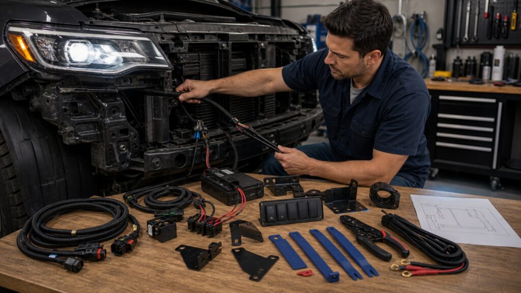
Buying framework
Draw the current path and force path first
A wiring diagram and mount sketch expose conflicts before holes are drilled or factory circuits are tapped.
Inventory every load: Record lamp quantity, rated voltage, operating current, inrush behavior, duty cycle, and whether heaters, fans, or position lights add separate loads.
Choose an independent protected feed: Use the factory circuit only as a control signal when appropriate; size the new power path and fuse for the actual conductor and environment.
Map control logic: Determine whether the vehicle provides switched positive, switched ground, PWM, multiplexed control, or diagnostic monitoring before selecting a relay or interface.
Locate structure and service points: Mount into adequate structure, preserve adjuster access, and leave fuses and connectors reachable without dismantling unrelated equipment.
Who this is for
Match the installation architecture to system complexity
A pair of modest lamps on an older truck and a multi-zone system on a monitored vehicle need different controls and documentation.
Simple single-function installs: A correctly sized fused relay harness may be sufficient when the trigger is conventional and lamp current is predictable.
Modern monitored vehicles: Use interfaces documented for PWM, bulb-out diagnostics, smart alternators, and module behavior; improvised loads can create flicker or faults.
Multi-zone off-road systems: A sealed distribution or solid-state controller can simplify staged switching, current limits, labels, and fault isolation when designed for the combined load.
Harsh-environment users: Prioritize connector sealing, drip loops, abrasion sleeves, corrosion-resistant terminals, strain relief, and brackets resistant to repeated washboard vibration.
What to pay attention to
Installation specifications that prevent hidden failures
Wire gauge alone is not a system design. Circuit length, termination quality, control behavior, and structural stiffness all matter.
Electrical Architecture
Current, conductor capacity, voltage drop, protection, switching, grounding, and diagnostics.
Mechanical Architecture
Bracket span, fastener support, vibration, adjustability, corrosion isolation, and service access.
Current and conductor capacity: Size the complete out-and-back circuit for load, length, temperature, bundling, and acceptable voltage drop rather than copying a generic gauge chart.
Fuse coordination: Place overcurrent protection near the energy source and below the safe capacity of the downstream conductor and weakest intentional link.
Relay or controller rating: Check continuous and inrush capacity, environmental rating, contact suppression, standby draw, and behavior after a fault or low-voltage event.
Connector and ground design: Use compatible terminals, proper crimp tooling, seals, strain relief, and a ground path capable of carrying full load without relying on painted or corroded panels.
Bracket stiffness and aim range: Short supported spans, appropriate material thickness, locking hardware, corrosion control, and accessible adjusters help the beam stay stable.
Avoid these traps
Clean-looking installations that fail under load
Cosmetic neatness can hide undersized protection, poor terminations, noisy triggers, or flexible mounts.
Fusing for the lamp instead of the wire: An oversized fuse may let a damaged conductor overheat before protection opens; the branch protection must defend the installed wiring.
Using quick taps on critical wiring: Unsealed displacement taps can damage strands, admit moisture, and confuse monitored circuits. Use a documented interface and serviceable, sealed connection strategy.
Grounding wherever a bolt is convenient: Paint, seam sealer, mixed metals, loose sheet metal, and shared high-current paths can create voltage loss, heat, noise, or intermittent operation.
Mounting to a flexible skin: A lamp on a long bracket or thin panel can oscillate, blur the beam, fatigue hardware, and lose aim even when the fasteners feel tight.
Decision guidance
Choose controls and mounts from the load map
Select the simplest architecture that safely handles the current, signal, environment, and number of lighting zones.
If the trigger is conventional: Use a documented relay harness with appropriate fuse, wire, connector, and ground capacity; keep lamp current out of a low-rated dashboard switch.
If the trigger is PWM or monitored: Choose a validated interface or controller rather than adding resistors or guessing which conductor can tolerate an extra load.
If several zones share power: Use a labeled fused distribution plan with calculated combined demand, load shedding, and charging-system margin.
If the mounting surface flexes: Shorten or triangulate the bracket, move to structure, reduce lamp mass, or choose a purpose-built mount before drilling.
Ownership & compatibility
Inspect the installation at its electrical and mechanical joints
Heat cycles, vibration, corrosion, and cable movement reveal weaknesses after the first drive, not on the workbench.
Perform an early reinspection: After initial heat and vibration cycles, check fastener torque as specified, wire chafe, connector seating, fuse temperature, voltage at the lamp, and beam aim.
Keep diagnostics legible: Label circuits, save diagrams and part numbers, carry the correct spare fuse, and record controller configuration so later faults do not require reverse engineering.
Watch for progressive symptoms: Flicker, delayed start, hot terminals, discoloration, water tracks, radio noise, beam shake, or repeat faults justify shutdown and diagnosis before continued use.
FAQ
Lighting wiring and mounting questions
These answers cover protection, controls, sealing, structure, and validation.
Does every auxiliary light need a relay?
Where should the lighting fuse be installed?
How much voltage drop is acceptable for vehicle lamps?
Can I use the factory high-beam wire as lamp power?
What makes an automotive connector weather resistant?
Why do auxiliary lamps shake even when bolts are tight?
Should the relay be installed with terminals facing down?
How should wires pass through a body panel?
What should I test after completing the installation?
Bottom line
A durable lighting system is engineered at every joint
Correct lamp selection is only one component. Protection, controls, routing, terminations, structure, and verification determine whether its performance survives real driving.
Map before buying: Document current, trigger behavior, cable length, mounting structure, and service access.
Protect both load paths: Fuse and seal the electrical path; stiffen and secure the mechanical path.
Verify under real conditions: Measure energized voltage, watch heat and vibration, confirm required-light behavior, and recheck aim.
Reading Shortcuts
Move from the lighting installation problem to a vehicle-compatible plan that can be installed and verified.
Decision Reminders
Keep the complete lighting installation system in view while comparing parts.
- Load: Count operating and startup current.
- Protection: Fuse the conductor near its source.
- Signal: Identify PWM or monitored triggers.
- Seal: Crimp, latch, strain-relieve, and drain.
- Structure: Keep brackets short and stiff.
- Service: Leave fuses and aimers accessible.
Glossary Snippets
Terms that separate useful performance from apparent compatibility.
When to Use a Top 10 Review
Use a lighting installation roundup only after the required function, vehicle interface, and operating limits are known.
- Problem defined: The visibility or mobility failure is specific.
- Vehicle mapped: Interfaces and limits are documented.
- Format chosen: The correct product family is settled.
- Evidence available: Finalists can be compared on relevant tests.
Have finalists already? Open a Comparison for a closer tradeoff.
When to Use a Comparison
Compare lighting installation finalists that solve the same defined problem on the same vehicle configuration.
- Application: Both match the exact vehicle and function.
- Performance: Evidence addresses the operating problem.
- Integration: Mounting and system effects are understood.
- Ownership: Inspection and service demands are acceptable.
Need a broader field? Use a Top 10 to form a shortlist.