
How to Choose OBD Diagnostic Tools for Installation and Wiring Requirements
An OBD connector can accept a plug while the diagnostic setup is still wrong for the job. Tight trim clearance can load the connector, a worn cable can interrupt communication, an occupied port can conflict with a telematics device, and low voltage can make a network problem look like failed electronics.
Choosing for installation and wiring work means tracing the entire path: vehicle DLC, power and grounds, protocol pins, cable or wireless VCI, scanner, and any computer used for service software. It also means recognizing the scanner's boundary. Module data can direct a circuit test, but terminal tension, voltage drop, continuity, and waveform integrity require the correct diagram and measurement tools.
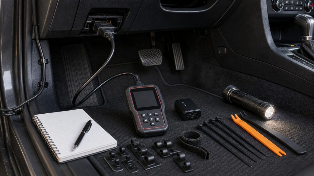
Buying framework
Audit the connection path before comparing functions
Treat every link between the vehicle network and the display as part of the diagnostic system. A stable scan begins with physical access and electrical integrity, then adds protocol support and the right measurement workflow.
Inspect the port environment: Locate the DLC, note covers and knee clearance, and check whether steering-column movement or trim presses on a straight plug. Plan a right-angle lead or approved extension only when it reduces strain without compromising communication.
Separate power from data: Verify connector supply and grounds before blaming software for a no-communication condition. A built-in voltage reading is a useful screen, but loaded voltage-drop tests require a meter and the correct circuit information.
Map the network path: Identify the protocols and any adapters used by the target vehicles, including legacy lines, CAN variants, or DoIP. The J1962 shell defines a connection; the VCI determines which signals it can handle.
Plan the supporting bench: Decide whether the job needs connector views, wiring diagrams, a breakout box, multimeter, oscilloscope, programming computer, or battery support. Buy the scanner as one instrument in that system.
Who this is for
Match the interface to the wiring work
Different users place different mechanical and electrical demands on the connection. Choose around where the display must sit, how often circuits are measured, and whether the port is already occupied.
The occasional code reader: An attached-cable handheld minimizes pairing and keeps data and power in one assembly. Look for a replaceable or well-protected lead if the unit will be stored tightly or used across several vehicles.
The accessory installer: You encounter trackers, remote-start systems, radios, cameras, and other additions that can affect power or networks. Favor quick full-system scans, voltage visibility, compact plugs, and access to diagrams that show the circuits being altered.
The electrical diagnostician: You need bidirectional commands and PIDs to create test conditions, then direct measurements to prove the circuit. A wireless VCI, diagram library, breakout accessories, and easy data recording can keep the meter and screen visible together.
The pass-through programmer: Your setup includes an approved J2534 interface, OEM application, compatible computer, stable wired connections, and specified battery support. Treat these as a controlled programming station, not an extension of ordinary scan-tool portability.
What to pay attention to
Connection details that prevent false diagnostic leads
The useful specifications describe fit, electrical visibility, communication support, and access to circuit information. Evaluate them on the hardest vehicle and working position you expect.
Physical & Electrical Connection
Check plug orientation, cable reach, pin condition, strain relief, DLC voltage, grounds, and how an occupied port will be handled.
Network & Measurement Workflow
Confirm protocols, VCI transport, wiring diagrams, connector views, test access, and programming infrastructure as one repeatable process.
Plug profile and retention: A compact or right-angle connector may clear trim and the driver's legs better than a deep dongle. It should seat fully without requiring force or placing sideways leverage on vehicle terminals.
Lead design: Choose enough length to place the screen where measurements can be seen, with strain relief at both ends and locking hardware where the VCI requires it. Replaceable leads suit high-cycle shop use.
Voltage indication: A cable voltmeter can reveal obvious low or high supply conditions at pin 16. It does not confirm ground quality under load or prove that communication conductors are intact.
Protocol hardware: Verify the interface supports the actual network carried at the connector, including any required CAN FD, DoIP, legacy, or brand-specific adapter path. Do not infer signal support from plug shape.
Diagram depth: Useful service information includes connector face orientation, terminal numbers, wire colors, splice and ground locations, expected values, and test conditions. A generic DTC definition is not a wiring plan.
Tethered fallback: Wireless VCIs improve movement, but a documented USB, Ethernet, or main-cable fallback is valuable for long sessions and programming. Confirm which link the OEM application supports rather than assuming every connection mode is interchangeable.
Avoid these traps
Wiring assumptions that create communication faults
Poor connection choices can imitate a module or network failure. Preserve terminal integrity and prove the electrical path before replacing electronics.
Forcing a crowded plug: Do not bend a dongle against trim or the driver's knee to make it fit. Reposition the vehicle controls as allowed, remove the proper access panel, or use an approved low-profile connection that seats squarely.
Trusting an unknown splitter: A splitter can change mechanical loading, expose unswitched power, or connect multiple devices that compete on the network. Verify the vehicle and device guidance; remove nonessential hardware when diagnosing communication.
Back-probing without a plan: Improvised probes can spread terminals, pierce insulation, or contact the wrong circuit. Use connector views, approved back-probes or a breakout fixture, and vehicle-specific precautions—especially around restraint and high-voltage systems.
Calling scan data a wire test: A fixed PID or lost module narrows the search but does not identify the open, short, resistance, or terminal problem. Confirm power, ground, signal, and network conditions with suitable instruments.
Decision guidance
Choose by connection complexity and proof required
Start with the physical layout and the electrical question the tool must help answer. Add interface sophistication only when it makes a defined measurement or service procedure more reliable.
If the port is clear and work is basic: Use an attached-cable handheld with durable strain relief and visible DLC voltage. Its fixed lead is simple, but make sure the screen can rest without pulling on the vehicle connector.
If cabin clearance is the main constraint: Select a low-profile adapter or an approved right-angle lead and confirm full seating in the actual vehicle. Avoid leaving the connector where a leg, pedal movement, or trim panel can strike it.
If circuit diagnosis is routine: Favor a platform with useful diagrams, connector views, active tests, and simultaneous PID display, then budget for a meter, back-probes, and breakout access. The supporting information may matter more than tablet size.
If module software will be written: Choose a verified J2534 interface for the OEM application and build the rest of the station around wired stability, approved cables, reliable internet, and specified vehicle power support.
Ownership & compatibility
Maintain the parts that carry power and data
Connector hardware degrades quietly, and software changes can alter interface behavior. A short inspection routine prevents avoidable no-communication calls.
Inspect high-cycle connections: Look for recessed or spread pins, cracked housings, loose locking screws, crushed leads, and weak strain relief. Retire damaged adapters instead of holding them at an angle during a scan.
Control adapters and installed devices: Label legacy connectors, extensions, and breakout leads by purpose, and document any tracker or telematics device removed for service. Restore only the original approved configuration after testing.
Keep the interface stack aligned: Maintain compatible scanner, VCI, driver, firmware, computer, and OEM software versions. Test wired fallback and vehicle power support before a programming appointment.
FAQ
Connection and wiring questions buyers should settle
Use the vehicle's service information and tool documentation to confirm any pin, adapter, or programming requirement.
Is every OBD-II connector wired the same way?
Can low battery voltage stop a scanner from communicating?
Should I buy an OBD extension cable?
Are OBD splitters safe for trackers and scanners?
Does a scan tool replace a digital multimeter?
When is a diagnostic breakout box useful?
Is a wireless VCI less reliable than a cable?
What wiring is required for J2534 programming?
Why does a scanner work when I move the plug?
Bottom line
A clean connection makes every feature more credible
Choose a scanner that fits the DLC without strain, supports the vehicle's real networks, and works alongside proper circuit measurements. Reliable power, cabling, information, and fallback connections are more valuable than a decorative accessory count.
Fit first: Confirm port clearance, plug retention, cable reach, and installed-device conflicts.
Prove electrically: Use diagrams and measurement tools to verify what scan data can only suggest.
Stabilize programming: Treat J2534 work as a controlled computer, interface, power, and software system.
Reading Shortcuts
Follow the diagnostic link from connector to measurement.
Decision Reminders
Verify these before connecting.
- Clearance: Seat the plug without trim or knee pressure.
- Pins: Inspect alignment and retention before blaming software.
- Voltage: Check supply and grounds under proper conditions.
- Protocol: Match the VCI to the vehicle network.
- Diagrams: Use connector views and test specifications.
- Fallback: Keep a supported wired path for critical sessions.
Glossary Snippets
Terms that separate connection from diagnosis.
When to Use a Top 10 Review
Use a roundup after mapping the physical and electrical connection.
- Filter: By plug geometry, lead design, and protocol support.
- Look for: Replaceable cables and documented adapters.
- Value: Diagrams and measurement workflow over accessory counts.
- Confirm: J2534 and wired fallback claims in documentation.
Already down to 2–3 options? A Comparison is usually the faster next step.
When to Use a Comparison
Compare finalists on the same difficult port and network.
- Fit: Test clearance and connector retention.
- Reach: Place the display without loading the DLC.
- Measure: Compare voltage visibility and diagram access.
- Recover: Verify cable replacement and tethered fallback.
Still exploring? Start with a Top 10 to build a shortlist first.