
How to Choose Radar Detectors for Installation and Wiring Requirements
A tidy wire can hide a weak installation. The receiver may sit off axis, its fuse may be unreachable, the ground may be noisy, or the cable may cross a curtain-airbag path. Those problems begin before the first trim panel is removed.
Choose the detector and installation as one package. Establish a legal RF-clear position, test alert visibility and mute reach, confirm electrical requirements, then map a protected circuit and reversible harness route from vehicle documentation. Permanent concealment should follow a temporary operational test, not substitute for one. This check keeps the installation grounded in the actual cabin.
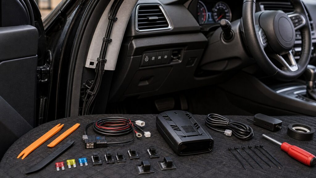
Buying framework
Prove position, power, and path before opening trim
Treat mounting location, electrical supply, harness route, and service points as four separate approvals.
Approve the antenna position: Confirm clear glass, level forward orientation, legal sightline, GPS reception, wiper clearance, bracket footprint, and mirror or camera movement.
Specify electrical demand: Record required voltage, current, connector, startup tolerance, sleep behavior, and whether the model supports a manufacturer-approved hardwire accessory.
Select circuit and protection: Use documented fuse-panel information to identify an appropriate feed, separate fuse, sound ground, and shutdown behavior without probing sensitive networks.
Draw the cable route: Keep wiring secured away from airbags, pedals, steering, heat, sharp edges, moisture, and moving trim while preserving labeled service access.
Who this is for
Match installation depth to the vehicle and owner
A removable cord, concealed lead, mirror bracket, and remote system demand very different labor and documentation.
Occasional removable user: A socket cord and suction mount minimize modification; prioritize stable placement, cord controls, safe storage, and verified ignition-off behavior.
Daily owner wanting concealed power: Use the exact approved hardwire kit and a documented protected circuit after the windshield position proves reliable.
Vehicle with constrained mirror area: Measure curved glass, housings, visors, and cameras before considering specialized brackets; never attach to safety-system covers.
Custom remote-system buyer: Require a qualified installer plan for external receivers, firewall passage, weather sealing, controller placement, diagnostics, and deinstallation.
What to pay attention to
Hardware details that separate clean work from hidden risk
Small physical specifications control antenna orientation, electrical reliability, and whether later service can reach the system.
Mount Geometry
Validate antenna alignment, glass transmission, sightline, bracket stability, control reach, GPS view, and removal.
Electrical Integration
Verify voltage, current, circuit state, fusing, grounding, airbag-safe routing, shutdown, interference, and access.
Bracket adjustment range: Body depth, windshield slope, joint travel, vibration resistance, cup or adhesive area, and cable exit determine whether the antenna remains level.
Hardwire compatibility: Model-specific voltage conversion, connector polarity, remote-mute support, and fuse requirements make generic cable substitution risky.
Circuit state: Accessory, ignition, retained-accessory, and constant feeds behave differently through startup, shutdown, charging, and sleep; test the full vehicle cycle.
Fuse and ground access: Protection should match the accessory and remain labeled and reachable; grounds need clean approved chassis connection rather than a convenient painted screw.
Airbag-safe routing: A-pillar and dash trim can conceal deployment paths, clips, sensors, and wiring; use vehicle service information or qualified installation.
Noise and cutoff behavior: Chargers, converters, poor grounds, and constant power can cause interference or battery drain; verify low-voltage protection and parked current where applicable.
Avoid these traps
Wiring shortcuts that defeat a good receiver
Most failures follow convenience choices made without circuit, airbag, glass, or access information.
Hardwiring before route testing: Temporary operation should prove reception, GPS, alerts, control reach, power cycles, and interference before permanent cable concealment.
Choosing a fuse by name alone: Fuse labels may not reveal retained power, monitoring, shared loads, or network sensitivity; confirm behavior with authoritative vehicle information.
Tucking wire beside an airbag: Loose cable or clips can alter deployment; keep harnesses outside specified zones and avoid blind trim probing.
Burying the only fuse or update lead: Future faults and firmware work should not require full dashboard disassembly; label and retain access points.
Decision guidance
Choose the least invasive dependable installation
Increase installation complexity only when it solves a demonstrated power, sightline, or reception problem.
If socket power behaves correctly: Keep the removable solution when cable placement is safe and appearance is acceptable; it preserves transfer and troubleshooting simplicity.
If only the dangling cord is objectionable: Hardwire the proven windshield position with the exact kit, protected circuit, accessible fuse, documented ground, and safe route.
If the preferred bracket does not fit: Choose a smaller supported mount or alternate approved zone rather than forcing off-axis alignment near mirrors or cameras.
If coated glass blocks reception: Investigate a purpose-built remote system and professional installation instead of hiding a portable behind trim.
Ownership & compatibility
Keep diagrams and access with the vehicle
Documentation prevents future technicians from treating a hidden accessory as an unexplained electrical fault.
Store an installation diagram: Record mount location, cable path, fuse slot and rating, ground, kit number, connector, serial, firmware, and removal sequence.
Inspect seasonal hardware: Temperature and vibration loosen cups, adhesive, joints, and connectors; re-level the antenna and replace weakened parts.
Retest after service: Battery, windshield, mirror, camera, trim, audio, or electrical work can change power and interference; repeat startup, shutdown, GPS, and alert checks.
FAQ
Installation questions to settle before hardwiring
Use exact detector, vehicle, and kit documentation when applying these answers.
Is hardwiring better than a socket cord?
Should detector power be switched or constant?
Can I use any USB cable or hardwire lead?
Where should the ground wire attach?
Is an add-a-fuse always acceptable?
Can wiring run behind the A-pillar trim?
How do I prevent battery drain?
Could hardwiring create false alerts?
What should remain accessible after installation?
Bottom line
Make the installation reversible and testable
A professional result remains level, protected, quiet, accessible, and removable after trim closes.
Approve the physical location: Verify glass, angle, sightline, stability, controls, GPS, cameras, and legal placement.
Engineer the electrical path: Match the kit, circuit, fuse, ground, shutdown, low-voltage behavior, and interference environment.
Preserve future access: Protect harnesses, label service points, store diagrams, and retest after related vehicle work.
Reading Shortcuts
Move through the mount engineering, protected power, harness routing, and future service access decision in order.
Decision Reminders
Neat wiring is valuable only when its engineering is visible in the records.
- Approve the antenna position: Verify and record this requirement.
- Specify electrical demand: Verify and record this requirement.
- Select circuit and protection: Verify and record this requirement.
- Store an installation diagram: Verify and record this requirement.
- Inspect seasonal hardware: Verify and record this requirement.
- Retest after service: Verify and record this requirement.
Glossary Snippets
Terms used in this detector plan.
When to Use a Top 10 Review
Use rankings only after the requirements are fixed.
- Approve the physical location: Use this as a shortlist filter.
- Engineer the electrical path: Use this as a shortlist filter.
- Preserve future access: Use this as a shortlist filter.
- Exclude: Use this as a shortlist filter.
Already down to 2–3 options? A Comparison is usually the faster next step.
When to Use a Comparison
Compare finalists against the same route, vehicle, settings, and power test.
- Approve the antenna position: Test this point on both finalists.
- Specify electrical demand: Test this point on both finalists.
- Select circuit and protection: Test this point on both finalists.
- Draw the cable route: Test this point on both finalists.
Still exploring? Start with a Top 10 to build a shortlist first.