
How to Choose Towing, Trailers & Hauling for Trailer Wiring and Braking
Trailer lighting and braking share a connector, but they are not one simple circuit. The trailer may need only basic lamps, or it may add electric brakes, auxiliary power, reverse, a controller, and an independent breakaway arrangement. Each function needs a verified path through the vehicle and trailer.
Start with the installed brake technology and applicable requirements, then map pins, grounds, current capacity, protection, controller behavior, and emergency power. Finish with mechanical brake inspection and a loaded functional test. A plug that fits and lamps that glow are only the beginning.
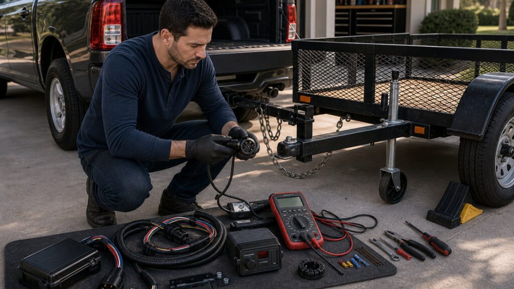
Buying framework
Map every circuit and braking function
A trailer connector is only the interface. Build the system from required lamps and brakes back through the trailer harness, connector, vehicle integration, controller, protection, and emergency power.
Identify the trailer brake system: Determine whether the trailer is unbraked, electric drum, electric-over-hydraulic, surge hydraulic, or another supported design. Record axle count, brake manufacturer, loaded weight, controller requirements, adjustment method, and applicable legal thresholds before selecting electronics.
List connector functions by pin: Map ground, tail and marker lamps, left and right stop or turn, electric-brake output, auxiliary power, reverse, and any other supported circuit. Do not infer a pinout from shell shape or wire color; verify both vehicle and trailer documentation.
Choose the vehicle interface: Check for factory tow wiring, a vehicle-specific harness, powered converter, required fuses or relays, network monitoring, and approved brake-controller connections. Modern lamp circuits may need an isolated module rather than direct splicing into vehicle wiring.
Plan control and emergency braking: Match a controller to the brake technology, vehicle, axle count, mounting or calibration needs, manual control, and fault reporting. Verify the breakaway switch, cable, battery or power source, charger, and test method required by the trailer manufacturer and law.
Define a functional test sequence: Test grounds and each lighting circuit, confirm brake output and controller communication, inspect breakaway operation according to instructions, calibrate or adjust in a safe location, and recheck after loading. Passing lamps alone is not proof of usable trailer brakes.
Who this is for
Match electrical complexity to the trailer
Water exposure, brake technology, tow-vehicle electronics, and trailer interchangeability change what a reliable wiring system needs.
Small unbraked utility-trailer owners: Basic lighting may use a four-way connector, but ground quality, protected routing, connector strain relief, lamp visibility, and vehicle-specific conversion still matter. Verify legal brake requirements before assuming the trailer qualifies as unbraked in every loaded condition.
Electric-brake travel and cargo users: A seven-way circuit, compatible controller, brake output, auxiliary power where required, breakaway equipment, brake adjustment, and loaded gain setup form one system. Integrated and aftermarket controllers must be checked against the exact vehicle and trailer brakes.
Boat-trailer users: Surge brakes avoid an electric output circuit in some designs, while electric-over-hydraulic systems may need a compatible controller. Immersion increases attention to sealed routing, grounds, connector handling, corrosion, breakaway parts, and the brake manufacturer's post-launch maintenance.
Multi-trailer and fleet operators: Standardized pinouts, labeled adapters, controller profiles, common breakaway batteries, protected junction boxes, and repeatable pre-trip tests reduce cross-connection errors. Each trailer still needs its own loaded brake setting and inspection record.
Tow-vehicle retrofit buyers: Aftermarket wiring should be selected by vehicle application, lamp architecture, connector functions, current demand, and brake-controller provisions. Use approved harness paths and qualified installation when splicing, coding, network integration, or safety-system interaction exceeds the instructions or operator's skill.
What to pay attention to
Electrical and brake specifications that must align
Compare circuit functions, current paths, controller behavior, brake hardware, and emergency operation. Product compatibility tables are more valuable than universal labels.
Circuit & Vehicle Integration
Connector functions, current capacity, grounds, converters, factory modules, protection, diagnostics, routing, and corrosion.
Brake Control & Emergency Function
Brake technology, controller response, gain, manual control, breakaway equipment, adjustment, testing, and legal requirements.
Four-way and seven-way functions: A four-way commonly supports ground, tail or marker, and combined stop or turn circuits. A seven-way can add electric brakes, auxiliary power, and reverse, but pin standards, adapters, and vehicle activation must be confirmed for both ends.
Ground path and voltage drop: Lights and brakes depend on a low-resistance return path. Inspect dedicated grounds, frame bonds where specified, connector contact, junctions, wire size, corrosion, and loaded voltage behavior. A continuity beep with no current may miss a poor connection.
Vehicle converter and protection: A powered converter can isolate trailer load from sensitive vehicle lamp circuits, while factory modules may monitor faults and require fuses, relays, or configuration. Match the harness to the vehicle and total lamp demand; never exceed circuit or module ratings.
Controller response and compatibility: Proportional controllers relate output to braking demand, while time-based designs follow a timed output curve; integrated systems use vehicle data. Confirm supported brake type, axle count, mounting orientation, calibration, manual override, diagnostics, and electric-over-hydraulic capability where needed.
Brake hardware and adjustment: Magnets, shoes, drums, actuators, hydraulic components, wiring, and adjustment determine actual braking. A powerful controller cannot correct contaminated friction surfaces, open circuits, poor grounds, seized hardware, air, leaks, or incorrect mechanical adjustment.
Breakaway equipment: Match switch, lanyard routing, wiring, battery type and capacity, charging method, test interval, and brake system under trailer instructions and applicable requirements. The cable must operate independently of normal coupling without dragging or snagging.
Connector durability and routing: Look for secure strain relief, weather protection, replaceable contacts where supported, protected junctions, grommets, abrasion resistance, drip management, and clearance from exhaust, suspension, sharp edges, pinch points, and launch-water immersion.
Avoid these traps
Wiring and braking assumptions that fail under load
Physical connection and illuminated lamps are easy checks; the braking path needs deeper verification.
Matching by plug shape alone: Two seven-way connectors can be wired incorrectly, lack activated circuits, or use adapters that omit brake or auxiliary functions. Verify the pinout and loaded operation at both ends instead of treating mechanical fit as electrical compatibility.
Trusting wire colors universally: Color conventions vary across vehicles, trailers, repairs, and aftermarket harnesses. Trace functions with diagrams and suitable test equipment, label verified conductors, and do not connect a circuit solely because two colors happen to match.
Testing only the trailer lamps: Turn, stop, and marker lights can work while brake output, breakaway power, auxiliary charge, reverse, or ground paths remain faulty. Test every required function and inspect brake hardware, then evaluate loaded response in a safe area.
Copying one gain setting forever: Trailer load, brake adjustment, friction condition, road surface, tires, and controller installation affect response. Set and verify gain under the controller and trailer instructions, and reassess after loading changes or brake service.
Using adapters as permanent problem solvers: An adapter may change connector format but cannot create missing vehicle circuits, controller compatibility, adequate current capacity, or a good ground. Identify which functions pass through and protect the connection from leverage, moisture, and accidental separation.
Decision guidance
Choose the wiring path from brake technology outward
Start at the trailer brakes and required circuits, then select the connector, controller, and vehicle interface that support them without improvisation.
If the trailer needs only basic lighting: Use a vehicle-specific four-way solution when it provides the required ground, marker, stop, and turn functions and the loaded trailer legally and mechanically needs no additional circuits. Protect the harness and test at the connector and lamps.
If the trailer has electric brakes: Choose a compatible seven-way path, controller, breakaway system, and brake wiring for the exact vehicle, brakes, and axle count. Verify factory activation, fusing, ground, output, adjustment, and loaded gain rather than assuming a tow package includes everything.
If the trailer uses surge brakes: Confirm the coupler actuator, hydraulic brakes, reverse-lockout or free-backing arrangement, breakaway requirements, and connector functions under the manufacturer instructions. A conventional electric-brake controller may not operate the surge system.
If the trailer uses electric-over-hydraulic brakes: Verify that both the controller and vehicle integration explicitly support the actuator. Check required power, ground, breakaway arrangement, hydraulic condition, bleeding, and diagnostic behavior; plug compatibility alone cannot establish controller-actuator communication.
If vehicle integration is uncertain: Use the vehicle maker's tow documentation, harness application guide, controller compatibility list, and a qualified installer. Stop before tapping unknown circuits or altering safety-related vehicle wiring without a supported method and suitable testing.
Ownership & compatibility
Keep current paths clean and brake response repeatable
Electrical faults often grow at exposed connections, grounds, flexible wire runs, and infrequently tested emergency components.
Inspect from connector to brake: Check blades or pins, socket tension, caps, strain relief, junctions, grounds, loom, axle crossings, flex points, magnets or actuators, hydraulic lines, and lamps. Repair chafing, corrosion, heat damage, loose terminals, or leaks using supported parts and methods.
Maintain the brake mechanism: Follow the brake maker for adjustment, friction inspection, drum or rotor condition, bearings where related, hydraulic fluid, bleeding, actuator service, and burnishing or bedding. Controller output cannot compensate for neglected mechanical brakes.
Test breakaway readiness: Inspect cable routing, switch movement, battery condition, charging, connections, and brake application at the prescribed interval. Replace damaged or depleted parts and never use the breakaway cable as a substitute safety chain.
Record each trailer's setup: Keep pinout, controller profile, gain procedure, brake type, service dates, test results, and recurring faults with the trailer. For fleets, label approved adapters and prevent drivers from silently using a profile created for another load.
FAQ
Trailer wiring and braking FAQ
Answers about connectors, controllers, grounds, breakaway systems, and functional tests.
Do I need a four-way or seven-way trailer connector?
Will any brake controller work with any trailer?
Why do trailer lights flicker or dim?
Can I trust standard trailer wire colors?
What does trailer brake gain control?
How is a proportional controller different from a timed controller?
What is the purpose of a breakaway battery?
Should I disconnect boat-trailer wiring before launching?
What should I test before towing a braked trailer?
Bottom line
Verify functions, not just connections
A reliable trailer electrical system carries the correct signal and current through protected wiring, operates compatible brakes, and preserves emergency braking when the normal connection is lost.
Start with brake technology: It determines controller, power, breakaway, adjustment, and test requirements.
Map every connector pin: Confirm function at both vehicle and trailer rather than trusting shape or color.
Test under realistic conditions: Inspect hardware, set gain, verify loaded response, and watch for voltage or ground faults.
Maintain exposed components: Connectors, flexible runs, grounds, brakes, and emergency batteries need recurring attention.
Reading Shortcuts
List every lamp, brake, power, and emergency function.
Decision Reminders
Checks to complete before the combination moves.
- Identify brake type: Electric, surge, and EOH need different control.
- Verify the pinout: Shape and color do not prove function.
- Test the ground: Return-path resistance affects lights and brakes.
- Check controller support: Vehicle and actuator compatibility matter.
- Test breakaway power: Normal braking does not prove emergency function.
- Recheck after loading: Gain and response can change.
Glossary Snippets
Terms used in this towing decision.
When to Use a Top 10 Review
Use rankings once the connector functions, brake technology, and vehicle interface are defined.
- Brake type is known: Compare only compatible controller families.
- Required circuits are mapped: Avoid adapters that omit essential functions.
- Vehicle integration is checked: Screen harnesses by exact application.
- Test method is planned: Favor clear diagnostics and service access.
Already down to 2–3 options? A Comparison is usually the faster next step.
When to Use a Comparison
Compare finalists with the same vehicle, trailer brakes, axle count, and required circuits.
- Compare compatibility: Review controller and actuator support.
- Compare diagnostics: Look for useful fault and connection feedback.
- Compare installation: Evaluate harnessing, calibration, and routing.
- Compare ownership: Check connectors, batteries, service parts, and records.
Still building a shortlist? Start with a Top 10.