
How to Choose Vehicle Security Systems for In-Dash Upgrade Planning
A concealed security system still needs to communicate, sense movement, sound outside the cabin, accept an emergency override, receive firmware service, and come apart for diagnosis. Burying every component in the deepest dashboard cavity can weaken several of those jobs at once.
Plan locations by function before removing trim. The control module needs a protected environment and secure fastening; antennas need radio and satellite exposure; sensors need representative mounting surfaces; fuses, valet controls, and update leads need controlled access. A professional installation looks discreet to a thief but remains intelligible to its owner and technician.
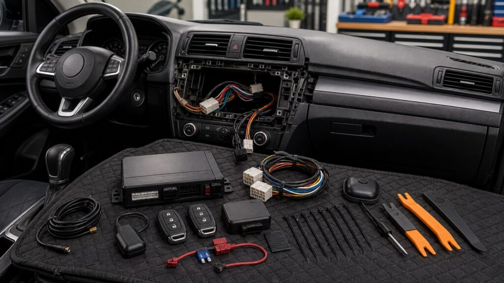
Buying framework
Assign component zones before hiding the system
Every module receives a location requirement for environment, signal, sensing, interaction, protection, and access.
Zone each component: Mark dry protected control space, RF-clear antenna glass, GPS view, representative sensor surfaces, exterior siren area, visible LED, and reachable override.
Map power and signals: Identify fused feeds, grounds, CAN interface, discrete triggers, locks, siren, lights, starter interrupt, hood safety, antennas, and cellular wiring.
Protect the harness: Route outside airbags, pedals, steering, heat, sharp edges, moisture paths, moving panels, factory service points, and high-current or noisy wiring.
Reserve service access: Provide labeled fuses, connectors, update lead, valet switch, diagnostic LED, service loops, module removal order, and safe system deactivation.
Who this is for
Match concealment depth to ownership and risk
A simple alarm, remote-start combination, and cellular recovery network justify different cabin and exterior work.
Basic concealed alarm buyer: A protected control module, accurate triggers, calibrated sensor, siren, LED, override, and documented fuse may meet the need.
Two-way remote owner: Antenna height and orientation, RF cable protection, remote programming access, and range testing add visible design constraints.
Security plus remote-start buyer: Immobilizer interface, hood switch, brake and gear interlocks, takeover, shutdown, engine sensing, and service mode increase integration depth.
Cellular recovery subscriber: GPS and cellular antennas, backup power, account pairing, update access, status diagnosis, and long-term module replacement must remain serviceable.
What to pay attention to
Installation details that control range, sensing, and service
Physical placement changes RF range, sensor response, siren output, electrical reliability, and repair time.
Component Zoning
Assign dry, cool, secure, RF-clear, audible, visible, sensing, and serviceable locations to each module before disassembly.
Harness & Recovery
Engineer fused power, grounds, protected routes, triggers, interruption, strain relief, labels, diagnostics, override, update access, and removal.
Control-module location: Choose a secure dry moderate-temperature area with solid fastening, connector strain relief, limited casual visibility, and a documented removal path.
Antenna exposure: RF remotes, cellular, and GPS have different placement needs; metal, tint, defroster traces, factory electronics, and bundled cables can reduce performance.
Sensor mounting: Shock sensors need a representative rigid structure; tilt and glass sensors follow their own orientation and acoustic rules; temporary testing precedes final fastening.
Siren and hood hardware: Use weather-conscious downward-facing siren placement, protected wiring, and a reliable hood switch where required, away from heat, moving parts, and water traps.
Interruption and power: Starter or ignition changes require exact-vehicle safe design, appropriate relays, correct fusing, sound grounds, sleep-current testing, and clear emergency bypass.
Visible and service controls: Place LED and valet or programming controls discreetly but accessibly; preserve update ports, backup-battery connections, diagnostics, and installer labels.
Avoid these traps
Concealment mistakes that create fragile security
Deep burial without validation can trade theft resistance for weak signals, nuisance alarms, or destructive maintenance.
Mounting antennas beside metal: Deep dash structure or coated glass can shorten remote, cellular, or GPS performance; test final orientation before fastening trim.
Putting every service point in one hidden bundle: A thief may find it, while technicians face tangled diagnostics; distribute securely but document fuses, controls, connectors, and paths.
Fastening sensors before calibration: Mounting surface and orientation change response; temporary placement and realistic trigger tests should precede permanent adhesive or screws.
Cutting factory wiring without a restoration plan: Every connection and interruption needs correct method, protection, labels, diagrams, and a reversible path for service or resale.
Decision guidance
Choose a layout that can still be diagnosed
Use the least invasive layout that meets threat coverage and exact-vehicle integration needs.
If only local alarm coverage is needed: Use a compact protected layout with complete perimeter triggers, one well-tuned sensor, siren, LED, override, and accessible fuse.
If remote range matters: Prioritize antenna placement and cable integrity before deeper module concealment; validate from actual parking locations and building conditions.
If remote start is included: Choose an integrated exact-vehicle platform and qualified installer with documented safety interlocks, takeover, shutdown, and immobilizer preservation.
If tracking and recovery are included: Reserve RF-transparent antenna zones, backup power, update access, account records, and a replaceable cellular module with known service terms.
Ownership & compatibility
Preserve diagrams, overrides, updates, and removal access
Documentation and reachable service points keep concealed electronics from becoming an unexplained future fault.
Keep a sealed installation record: Store photographs, diagram, wire functions, fuse, grounds, module and antenna locations, firmware, sensor settings, PINs, and removal order securely.
Test after adjacent work: Dashboard, windshield, audio, battery, body, hood, key, or dealer-software service can disturb hidden parts; repeat complete arming and sleep tests.
Plan transfer or removal: Know which modules and subscriptions move to another vehicle, how factory wiring is restored, and who erases accounts, keys, phones, and location history.
FAQ
In-dash security questions before trim removal
Final placement follows the exact platform and vehicle manuals, not these general answers alone.
Where should the alarm control module be hidden?
Where should the RF antenna be mounted?
Should the status LED be visible?
How accessible should the valet switch be?
Where should the siren be installed?
Can a shock sensor be hidden anywhere?
Is starter interruption safe?
What wiring should remain accessible?
Will concealed security affect future repairs?
Bottom line
Hide the system from view, not from service
Good concealment preserves reliable signals, calibrated sensing, safe wiring, emergency control, and future removal.
Place by function: Give receivers exposure, sensors representative surfaces, sirens safe exterior output, and control modules protected environments.
Wire for safety: Fuse correctly, preserve grounds and factory systems, avoid airbags and hazards, secure harnesses, and measure parked current.
Design the service path: Document overrides, diagnostics, updates, fuses, connectors, module access, restoration, subscriptions, and eventual removal.
Reading Shortcuts
Move through the concealed but serviceable integration across cabin, engine-bay, RF, power, trigger, and control zones decision in order.
Decision Reminders
Discreet installation and serviceability are complementary requirements.
- Zone each component: Verify and record this requirement.
- Map power and signals: Verify and record this requirement.
- Protect the harness: Verify and record this requirement.
- Keep a sealed installation record: Verify and record this requirement.
- Test after adjacent work: Verify and record this requirement.
- Plan transfer or removal: Verify and record this requirement.
Glossary Snippets
Terms used in this security system plan.
When to Use a Top 10 Review
Use rankings only after the requirements are fixed.
- Place by function: Use this as a shortlist filter.
- Wire for safety: Use this as a shortlist filter.
- Design the service path: Use this as a shortlist filter.
- Exclude: Use this as a shortlist filter.
Already down to 2–3 options? A Comparison is usually the faster next step.
When to Use a Comparison
Compare finalists against the same arming, trigger, notification, disarm, start, sleep-current, and service-mode sequence.
- Zone each component: Test this point on both finalists.
- Map power and signals: Test this point on both finalists.
- Protect the harness: Test this point on both finalists.
- Reserve service access: Test this point on both finalists.
Still exploring? Start with a Top 10 to build a shortlist first.