
Lighting & Visibility Buying Guide for Camera and Sensor Integration
Modern vehicles see through several different systems. A windshield camera may support lane functions and automatic high beams. Radar can sit behind a grille emblem or bumper surface. Ultrasonic sensors occupy painted bumper circles, while rear cameras depend on a usable image in uneven light.
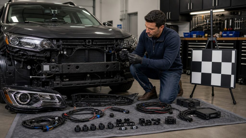
Map those systems before placing a lamp or bracket. Physical clearance is only the first check: light can reflect from the hood, plate, spare tire, trailer, or dust and overwhelm a camera. Wiring and electronic drivers can add faults or interference. Removing a bumper or changing ride height may create inspection or calibration work. Choose documented mounting zones, preserve factory covers and cleaning paths, and verify every affected system after installation.
Buying framework
Map sensing fields before drawing lighting zones
Treat cameras, radar, ultrasonic sensors, and automatic controls as installed equipment with optical, physical, electrical, and calibration boundaries.
Inventory the sensing suite: Use the owner and service information to locate front, rear, side, mirror, windshield, bumper, grille, and ambient-light sensors for the exact trim.
Draw obstruction and reflection paths: Project lamp body, bracket, cable, beam, hood reflection, plate reflection, dust, spray, and snow across each sensor field.
Preserve designed surfaces: Do not cover, repaint, drill, coat, or relocate radar covers, camera glass, ultrasonic faces, washers, heaters, or surrounding geometry without approved procedures.
Plan commissioning before disassembly: Determine which scans, inspections, initialization, aiming, static targets, or dynamic calibration follow lamp, bumper, windshield, suspension, or module work.
Who this is for
Match integration depth to the sensor risk
A reverse lamp near a simple camera differs from a grille bar near radar or an adaptive headlamp tied to steering and camera data.
Rear-camera improvers: Prioritize even low-glare illumination, plate and bumper reflection control, camera cleanliness, legal reverse-lamp function, and image checks in rain.
Grille and bumper installers: Map radar-transparent covers, ultrasonic cones, airflow, crash structures, tow points, and calibration access before using a universal bracket.
Roof and hood-light users: Control windshield and hood flare, automatic-high-beam camera exposure, rain-sensor areas, washer paths, cable routing, and wind vibration.
Adaptive-lamp replacements: Match modules, leveling, steering inputs, camera links, coding, and aim; a bolt-in housing may still need diagnostic commissioning.
What to pay attention to
Integration evidence beyond a no-obstruction claim
A safe layout preserves sensor geometry and also controls image exposure, electrical behavior, mechanical stability, and service procedures.
Perception Integrity
Field of view, radar path, ultrasonic cone, reflections, flicker, contrast, contamination, and automatic control.
Commissioning Integrity
Mount geometry, wiring noise, fault scans, module coding, initialization, aiming, and static or dynamic calibration.
Documented exclusion zone: Prefer vehicle-specific guidance showing allowable bracket and accessory areas instead of estimating from the visible sensor face.
Camera illumination quality: Look for even useful light without a central hot spot, plate flare, flicker bands, or bright surfaces that force exposure away from dark obstacles.
Radar and ultrasonic compatibility: Material, thickness, paint, fasteners, ice, mud, and nearby metal can affect detection; never treat visual transparency as radio-frequency transparency.
Electrical emissions and grounds: Quality drivers, shielded or routed cabling where specified, stable supply, correct grounds, and separation from sensor harnesses reduce interference risk.
Calibration and diagnostic support: The installer needs service procedures, target space or road conditions, compatible scan tools, and proof that calibration and fault checks completed.
Avoid these traps
Lighting integrations that leave sensors technically uncovered but functionally blind
Avoid layouts that pass a visual clearance check while introducing reflection, contamination, electrical noise, or changed geometry.
Judging from the sensor face alone: The detection field is wider than the visible lens or cover, and nearby metal, paint, brackets, or cable loops can still affect operation.
Adding excessive reverse light: A bright center spot or illuminated license plate can wash out nearby image detail while dark corners remain invisible.
Mounting without a contamination plan: A bracket can trap snow, channel washer fluid, collect mud, or make the camera and radar cover difficult to clean.
Assuming no warning means no problem: Some degradation changes detection range or image quality before a persistent dashboard fault appears. Functional checks and scans are still necessary.
Decision guidance
Choose the lighting position with the lowest sensing consequence
Move the lamp or reduce its optical ambition before modifying a factory sensor surface or calibration geometry.
If rear images are dark: Clean the camera and existing lamps, inspect exposure and aim, then add only even illumination that preserves required reverse-lamp operation and avoids plate flare.
If a grille mount crosses radar: Use a validated vehicle-specific location or relocate the lamp; do not cut or overlay the radar cover based on appearance.
If hood or windshield glare appears: Lower, shield, narrow, dim, or independently switch the offending zone rather than expecting software or the camera to adapt.
If body geometry must change: Obtain the service procedure and calibration plan first; budget scans, targets, alignment, ride-height setup, and a qualified facility before parts are ordered.
Ownership & compatibility
Keep sensors clean, aligned, and diagnostically visible
Accessory movement, minor impacts, dirt, snow, and software faults can change coexistence after the installation initially passes.
Create a cleaning route: Make camera glass, radar covers, ultrasonic faces, lamp lenses, washers, and vents reachable without bending brackets or disturbing aim.
Recheck after impacts and service: Scan and inspect after bumper contact, windshield replacement, suspension or tire changes, lamp removal, bracket movement, or recurring unavailable-system messages.
Record calibration evidence: Save pre- and post-scans, target setup, dynamic-calibration completion, ride-height data, aim results, and accessory configuration for later diagnostics.
FAQ
Camera and sensor integration questions
These answers address obstruction, reflections, electrical effects, and calibration.
Can an auxiliary light block radar even if it does not cover the sensor?
Why can brighter reverse lights make the camera image worse?
Do LED lights create interference with cameras or radar?
Will the vehicle always display a warning if a sensor is obstructed?
Can I mount lights in front of a grille emblem?
Does removing a bumper require driver-assistance calibration?
How can I reduce hood glare from auxiliary lights?
Can a lighting bracket interfere with ultrasonic parking sensors?
What should I verify after sensor-adjacent lighting work?
Bottom line
Lighting should add information without taking information away
The best integration preserves every sensing field, controls reflections and electrical effects, and leaves a documented path for diagnostics and calibration.
Map the suite: Identify cameras, radar, ultrasonic zones, covers, cleaners, and control sensors.
Control interactions: Test obstruction, reflection, image exposure, contamination, wiring noise, and bracket movement.
Commission the vehicle: Complete scans, functional checks, aim, initialization, and calibration the service procedure requires.
Reading Shortcuts
Move from the sensor-integrated lighting problem to a vehicle-compatible plan that can be installed and verified.
Decision Reminders
Keep the complete sensor-integrated lighting system in view while comparing parts.
- Map: Locate every sensor on the exact trim.
- Field: Allow more than visible-lens clearance.
- Reflection: Check hood, plate, glass, and wet road.
- Noise: Route and ground drivers carefully.
- Geometry: Bumper and ride height can matter.
- Proof: Save scans and calibration records.
Glossary Snippets
Terms that separate useful performance from apparent compatibility.
When to Use a Top 10 Review
Use a sensor-integrated lighting roundup only after the required function, vehicle interface, and operating limits are known.
- Problem defined: The visibility or mobility failure is specific.
- Vehicle mapped: Interfaces and limits are documented.
- Format chosen: The correct product family is settled.
- Evidence available: Finalists can be compared on relevant tests.
Have finalists already? Open a Comparison for a closer tradeoff.
When to Use a Comparison
Compare sensor-integrated lighting finalists that solve the same defined problem on the same vehicle configuration.
- Application: Both match the exact vehicle and function.
- Performance: Evidence addresses the operating problem.
- Integration: Mounting and system effects are understood.
- Ownership: Inspection and service demands are acceptable.
Need a broader field? Use a Top 10 to form a shortlist.