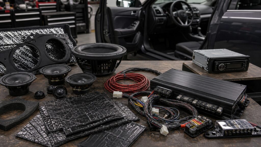
What Makes Car Audio Systems Different from Car Stereo Head Units

A car stereo head unit is a source-and-control component. It may provide radio, phone integration, media playback, display, navigation, decoding, volume, equalization, internal amplification, preamp outputs, and interfaces for cameras or vehicle controls. Its exact scope varies widely, especially when factory functions are distributed across multiple modules.

A car audio system includes every block required to turn the source into controlled sound: integration, signal transport, DSP, crossovers, amplifiers, protected power and ground, wiring, speakers, enclosures, mounting, cabin acoustics, tuning, and verification. Replacing the head unit changes one node and may leave the main limitation elsewhere.

By: Review Streets Research Lab
Updated: September 1, 2026
Explainer · 8-12 min read
car audio systems different from car stereo head units explainer hero image for Review Streets
What You'll Learn

Resolve Car Audio Systems and Stereo Head Units through Its Controlling Evidence

The comparison places the head unit inside the larger source-to-sound chain and assigns every external responsibility explicitly.

  • The Head Unit Is One Node; the Audio System Is the End-to-End Chain
  • Head Units Supply Digital, Preamp, or Speaker-Level Signals—not Guaranteed Speaker Performance
  • Vehicle Functions May Pass through the Head Unit, Interfaces, Amplifier, or Network
  • Head-Unit Tone Controls Differ from System-Level Channel Processing
  • Choose a Head Unit for Source and Control Needs; Change the System for Power, Coverage, or Acoustics
  • How to verify the finished state

Tip: Replace the component whose input, transformation, output, or limit actually fails; do not treat dashboard visibility as system scope.

Definitions

Key Concepts That Define Car Audio Systems and Stereo Head Units

The required terms mark the observable interfaces in this article: complete signal chain, source and control node, factory function retention, preamp or speaker output, external DSP routing, amplifier power stage, speaker load network, cabin acoustic response, protected power distribution, head-unit user interface, system-level tuning, component replacement boundary.

Complete Signal Chain

Complete Signal Chain locates the interface where car audio systems and stereo head units under the named surface and operating conditions.

  • Measure complete signal chain before work
  • Observe how complete signal chain changes
  • Record complete signal chain after verification

Source And Control Node

Source And Control Node sets the usable boundary for car audio systems and stereo head units under the named surface and operating conditions.

  • Measure source and control node before work
  • Observe how source and control node changes
  • Record source and control node after verification

Factory Function Retention

Factory Function Retention explains the material response during car audio systems and stereo head units under the named surface and operating conditions.

  • Measure factory function retention before work
  • Observe how factory function retention changes
  • Record factory function retention after verification

Preamp Or Speaker Output

Preamp Or Speaker Output measures the transfer created by car audio systems and stereo head units under the named surface and operating conditions.

  • Measure preamp or speaker output before work
  • Observe how preamp or speaker output changes
  • Record preamp or speaker output after verification

External Dsp Routing

External Dsp Routing reveals the failure condition within car audio systems and stereo head units under the named surface and operating conditions.

  • Measure external DSP routing before work
  • Observe how external DSP routing changes
  • Record external DSP routing after verification

Amplifier Power Stage

Amplifier Power Stage records the verified outcome after car audio systems and stereo head units under the named surface and operating conditions.

  • Measure amplifier power stage before work
  • Observe how amplifier power stage changes
  • Record amplifier power stage after verification

Tip: Use each term at its measured material, electrical, acoustic, or process boundary; record the related input and output before changing the system.

Scope Boundary

The Head Unit Is One Node; the Audio System Is the End-to-End Chain

The component manages sources and user commands, while the system includes upstream vehicle interfaces and downstream processing, power, transducers, acoustics, and electrical support. Evidence checkpoint 1 pairs complete signal chain with preamp or speaker output; speaker load network is the limiting observation. Record protected power distribution before changing system-level tuning, then repeat the complete signal chain reading after the system reaches a stable cooled, cleaned, powered, or tuned state. For row 229, source and control node establishes the input condition and amplifier power stage identifies the expected transformation. If head-unit user interface moves outside its limit first, hold preamp or speaker output constant and diagnose that interface instead of adding unrelated passes, pressure, gain, chemistry, or equalization. Scope test 1 marks complete signal chain inside the complete chain and assigns preamp or speaker output to the head-unit boundary. The observed state of speaker load network decides whether protected power distribution is a source-control issue or whether work must continue downstream through system-level tuning. The replacement record measures source and control node at the receiver output and amplifier power stage at the final acoustic result. A mismatch in head-unit user interface prevents a dashboard component from being blamed for external processing, power, transducer, wiring, or cabin limitations.

  • Draw the full chain
  • Mark the head-unit node
  • List external modules
  • Identify the actual bottleneck

One visible component does not define the whole architecture.

Output Boundary

Head Units Supply Digital, Preamp, or Speaker-Level Signals—not Guaranteed Speaker Performance

Output voltage, internal power, channel count, processing, clipping, and factory equalization determine what leaves the unit; amplifiers, loads, speakers, mounts, and cabin then determine sound. Evidence checkpoint 2 pairs source and control node with external DSP routing; cabin acoustic response is the limiting observation. Record head-unit user interface before changing component replacement boundary, then repeat the source and control node reading after the system reaches a stable cooled, cleaned, powered, or tuned state. For row 229, factory function retention establishes the input condition and speaker load network identifies the expected transformation. If system-level tuning moves outside its limit first, hold external DSP routing constant and diagnose that interface instead of adding unrelated passes, pressure, gain, chemistry, or equalization. Scope test 2 marks source and control node inside the complete chain and assigns external DSP routing to the head-unit boundary. The observed state of cabin acoustic response decides whether head-unit user interface is a source-control issue or whether work must continue downstream through component replacement boundary. The replacement record measures factory function retention at the receiver output and speaker load network at the final acoustic result. A mismatch in system-level tuning prevents a dashboard component from being blamed for external processing, power, transducer, wiring, or cabin limitations.

  • Identify output type
  • Measure usable range
  • Map channels
  • Avoid power assumptions

A feature-rich source can feed a weak downstream system.

Integration Boundary

Vehicle Functions May Pass through the Head Unit, Interfaces, Amplifier, or Network

Chimes, cameras, microphones, steering controls, climate displays, diagnostics, antennas, prompts, and amplifier turn-on can depend on vehicle-specific modules beyond the radio chassis. Evidence checkpoint 3 pairs factory function retention with amplifier power stage; protected power distribution is the limiting observation. Record system-level tuning before changing complete signal chain, then repeat the factory function retention reading after the system reaches a stable cooled, cleaned, powered, or tuned state. For row 229, preamp or speaker output establishes the input condition and cabin acoustic response identifies the expected transformation. If component replacement boundary moves outside its limit first, hold amplifier power stage constant and diagnose that interface instead of adding unrelated passes, pressure, gain, chemistry, or equalization. Scope test 3 marks factory function retention inside the complete chain and assigns amplifier power stage to the head-unit boundary. The observed state of protected power distribution decides whether system-level tuning is a source-control issue or whether work must continue downstream through complete signal chain. The replacement record measures preamp or speaker output at the receiver output and cabin acoustic response at the final acoustic result. A mismatch in component replacement boundary prevents a dashboard component from being blamed for external processing, power, transducer, wiring, or cabin limitations.

  • Inventory retained functions
  • Use supported interfaces
  • Verify before assembly
  • Check software behavior

Physical radio fit is not functional retention.

Tuning Boundary

Head-Unit Tone Controls Differ from System-Level Channel Processing

Basic bass, treble, balance, and fade may affect broad outputs; external DSP can route channels, set crossovers, delay speakers, equalize individual outputs, and tune a listening position. Evidence checkpoint 4 pairs preamp or speaker output with speaker load network; head-unit user interface is the limiting observation. Record component replacement boundary before changing source and control node, then repeat the preamp or speaker output reading after the system reaches a stable cooled, cleaned, powered, or tuned state. For row 229, external DSP routing establishes the input condition and protected power distribution identifies the expected transformation. If complete signal chain moves outside its limit first, hold speaker load network constant and diagnose that interface instead of adding unrelated passes, pressure, gain, chemistry, or equalization. Scope test 4 marks preamp or speaker output inside the complete chain and assigns speaker load network to the head-unit boundary. The observed state of head-unit user interface decides whether component replacement boundary is a source-control issue or whether work must continue downstream through source and control node. The replacement record measures external DSP routing at the receiver output and protected power distribution at the final acoustic result. A mismatch in complete signal chain prevents a dashboard component from being blamed for external processing, power, transducer, wiring, or cabin limitations.

  • Separate source settings
  • Establish clean gain structure
  • Tune crossovers first
  • Measure system response

More menus do not equal more usable processing.

Replacement Boundary

Choose a Head Unit for Source and Control Needs; Change the System for Power, Coverage, or Acoustics

A receiver upgrade may solve media and interface goals, while noise, weak bass, poor staging, distortion, or coverage may require integration, amplification, speakers, mounting, or tuning elsewhere. Evidence checkpoint 5 pairs external DSP routing with cabin acoustic response; system-level tuning is the limiting observation. Record complete signal chain before changing factory function retention, then repeat the external DSP routing reading after the system reaches a stable cooled, cleaned, powered, or tuned state. For row 229, amplifier power stage establishes the input condition and head-unit user interface identifies the expected transformation. If source and control node moves outside its limit first, hold cabin acoustic response constant and diagnose that interface instead of adding unrelated passes, pressure, gain, chemistry, or equalization. Scope test 5 marks external DSP routing inside the complete chain and assigns cabin acoustic response to the head-unit boundary. The observed state of system-level tuning decides whether complete signal chain is a source-control issue or whether work must continue downstream through factory function retention. The replacement record measures amplifier power stage at the receiver output and head-unit user interface at the final acoustic result. A mismatch in source and control node prevents a dashboard component from being blamed for external processing, power, transducer, wiring, or cabin limitations.

  • Name the failed function
  • Test the existing chain
  • Change the responsible block
  • Retune after replacement

Purchase scope should match the diagnosed limitation.

Quick Reality Check

Where Car Audio Systems and Stereo Head Units Helps—and Where It Stops

The method is defensible only while its named input, transformation, material or electrical limit, and verification evidence remain aligned.

Evidence Supporting Use

complete signal chain and source and control node remain controlled while factory function retention produces the expected material response.

preamp or speaker output, external DSP routing, and amplifier power stage can be observed independently without masking residue or an unstable finish.

Evidence Requiring a Stop

Stop when speaker load network, cabin acoustic response, or protected power distribution cannot be verified within the supported process window.

Unknown material, uncontrolled head-unit user interface, incompatible system-level tuning, or failed component replacement boundary requires another method, location, repair, or qualified service.

Common Myths

Misconceptions About Car Audio Systems and Stereo Head Units

Shortcuts about car audio systems and stereo head units often confuse complete signal chain with preamp or speaker output or ignore the limit imposed by speaker load network.

A premium head unit creates a premium audio system

Its source, interface, processing, and outputs matter, but amplifier power, impedance, speakers, enclosures, mounting, wiring, cabin acoustics, tuning, and electrical integrity still determine the result. Verify car audio systems and stereo head units on the named material after complete drying.

Replacing the radio automatically bypasses the factory amplifier

Many vehicles retain, require, or communicate with a separate factory amplifier; supported interfaces, channel routing, gain, prompts, and turn-on behavior must be confirmed. Check car audio systems and stereo head units against vehicle guidance and the observed residue.

More head-unit equalizer bands solve bad speaker placement

Equalization changes level by frequency but cannot repair blocked output, wrong polarity, rattles, weak mounting, missing bandwidth, excessive noise, or arrival-time geometry by itself. Confirm car audio systems and stereo head units with a controlled test before broader application.

A head unit is unnecessary when using a phone source

The system still needs safe source control, conversion or transport, volume strategy, processing, amplification, power, speakers, retained vehicle functions, and a driver-distraction-conscious interface. Reinspect car audio systems and stereo head units under stable light, temperature, and moisture conditions.

Tip: Challenge the claim by holding factory function retention stable, observing cabin acoustic response, and verifying system-level tuning before changing the system.

FAQ

Frequently Asked Questions About Car Audio Systems and Stereo Head Units

The answers below close the unresolved questions around source and control node, external DSP routing, protected power distribution, and the final evidence for component replacement boundary.

Can a head unit power aftermarket speakers directly?

Sometimes, when continuous output, impedance, sensitivity, crossover needs, channel count, wiring, listening level, and thermal limits fit; peak marketing power is not enough evidence. Document car audio systems and stereo head units, the affected surface, and the final functional check.

Why retain a factory head unit?

It may integrate vehicle display, climate, cameras, prompts, controls, microphones, networks, or styling; compatible processors and interfaces can sometimes upgrade downstream audio without removal. Keep car audio systems and stereo head units within the product label and recovery capacity.

When is head-unit replacement the right first step?

Choose it when source formats, controls, display, connectivity, decoding, preamp outputs, or retained-feature support are the diagnosed limitation and vehicle integration is feasible. Judge car audio systems and stereo head units by transferred soil rather than immediate appearance.

When is an amplifier more important?

Add or change amplification when speakers need more clean continuous power, channel topology, load stability, crossover control, or output headroom than the current path provides. Stop car audio systems and stereo head units when color, texture, grip, or adhesion changes.

How is the boundary verified?

Map every signal and vehicle function entering and leaving the head unit, then test downstream processing, power, speakers, wiring, acoustics, and tuning before assigning blame. Compare car audio systems and stereo head units with the untreated area after

Bottom Line

What Makes Car Audio Systems Different from Car Stereo Head Units depends first on complete signal chain, source and control node, and factory function retention; preamp or speaker output, external DSP routing, and amplifier power stage define the next controlled interface.

Close the decision only after speaker load network, cabin acoustic response, and protected power distribution remain compatible with head-unit user interface, system-level tuning, and component replacement boundary under the final operating test.

Next Steps

Continue the Car Audio Systems and Stereo Head Units Decision

Each destination extends a direct mechanism, fitment, or category boundary needed for the decision above; none is a taxonomy ancestor.

Quick Summary

Car Audio Systems and Stereo Head Units Explained

  • The Head Unit Is One Node; the Audio System Is the End-to-End Chain
  • Head Units Supply Digital, Preamp, or Speaker-Level Signals—not Guaranteed Speaker Performance
  • Vehicle Functions May Pass through the Head Unit, Interfaces, Amplifier, or Network
  • Head-Unit Tone Controls Differ from System-Level Channel Processing
  • Choose a Head Unit for Source and Control Needs; Change the System for Power, Coverage, or Acoustics