What Makes Right-Angle Drills Different from Standard Drills

Right-angle drills and standard drills share a common purpose, yet their structural differences reflect distinct mechanical priorities. The variation is not merely cosmetic; it involves motor orientation, gear reduction, torque transfer, and spatial access. Because both tools rotate drill bits and drive fasteners, they are often viewed as interchangeable, even though their internal configurations are engineered for different working geometries.

This explainer outlines how motor alignment, head design, torque delivery, and balance differ between right-angle and standard drills. It clarifies how each configuration manages rotational force and clearance constraints, providing a technical understanding of the mechanisms that separate these two drill systems.

By: Review Streets Research Lab
Updated: April 19, 2026
Explainer · 8–12 min read
Right-angle drill positioned next to a standard drill on a workbench highlighting the compact 90-degree head design used for tight spaces
What You’ll Learn

How Drill Orientation Changes Performance

A focused explanation of how motor alignment, gearing, and head geometry alter torque delivery, balance, and spatial access in different drill configurations.

  • How motor orientation redirects rotational force through angled gearing
  • Why a 90-degree head changes torque transfer and balance
  • How gear reduction compensates for compact internal layouts
  • What spatial clearance demands from tool geometry and housing design
  • How handle alignment affects leverage and operator-applied force
  • Why head length and offset alter drilling angles in confined framing
  • How internal components manage heat within tighter mechanical envelopes

Tip: Think in terms of force redirection: changing motor orientation reshapes how torque travels from motor to bit.

Definitions

Core Components That Separate These Drill Designs

Understanding how orientation, gearing, and housing geometry interact makes the structural differences between these two drill formats far easier to interpret.

Motor Orientation

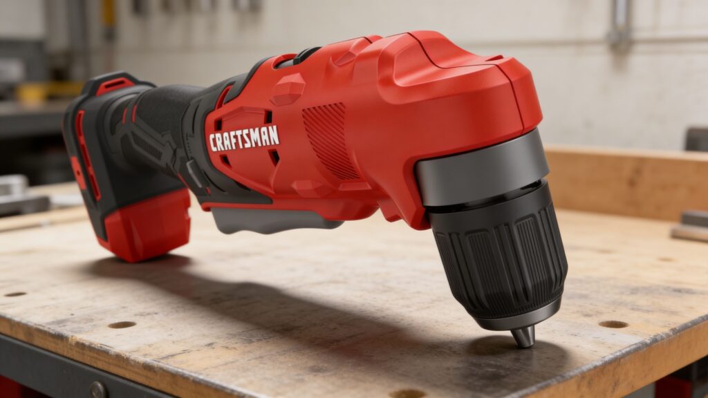
The direction the motor sits inside the housing determines how rotational force travels to the chuck. Inline layouts send power straight forward, while angled layouts redirect it through gearing.

  • Inline alignment: Motor shaft runs parallel with the bit
  • Perpendicular alignment: Motor sits at 90 degrees to the chuck
  • Force path: Orientation dictates how torque is transmitted internally

Right-Angle Gear Set

In angled drills, a gear set changes the direction of rotation from the motor to the chuck. This redirection requires compact, high-load gearing within a confined head assembly.

  • Bevel gears: Redirect rotational motion at a 90-degree junction
  • Load concentration: More stress focused inside the head
  • Compact housing: Gears must fit within tight dimensional limits

Head Geometry

The shape and length of the drill head determine how close the chuck can operate near obstructions. Reduced head length enables access between framing members and inside cavities.

  • Profile height: Controls vertical clearance in narrow bays
  • Offset distance: Affects reach near adjacent surfaces
  • Housing thickness: Influences structural rigidity under torque

Torque Transfer System

Both drill types rely on gear reduction to convert motor speed into usable torque, but angled systems must account for directional change and additional mechanical interfaces.

  • Speed reduction: Multiplies torque from high motor RPM
  • Energy loss: Extra gears introduce additional friction points
  • Structural support: Bearings stabilize redirected rotational forces

Handle Alignment

The position of the handle relative to the bit axis shapes how force is applied by the operator. Alignment changes leverage and reaction torque felt during drilling.

  • Centerline grip: Inline drills align hand and bit axis
  • Offset grip: Angled drills shift force application sideways
  • Reaction forces: Torque feedback varies with handle position

Clearance Envelope

The clearance envelope refers to the physical space the tool requires to operate. Different motor and head configurations expand or compress this usable working radius.

  • Rotational arc: Space needed for the body to turn
  • Bit projection: Forward extension beyond the housing
  • Obstruction tolerance: Ability to function near framing or cabinetry

Tip: View each drill as a torque-routing system: motor position, gears, and housing geometry collectively define how force reaches the bit.

Power Path

How Motor Orientation Redirects Rotational Force

The defining difference between these drill formats begins with how rotational energy travels from motor to chuck. Orientation determines whether force moves in a straight line or is redirected through angled gearing.

  • Inline designs transmit rotation directly along the bit’s axis
  • Right-angle layouts redirect rotation through a 90-degree gear interface
  • Additional gear interfaces introduce friction and load concentration
  • Housing structure must support redirected torque under sustained stress

The chosen force path ultimately shapes how efficiently torque reaches the bit under load.

Motors

How Motor Position Influences Balance and Torque Reaction

Motor placement affects more than internal layout; it alters the tool’s center of mass and the direction of reaction forces during drilling. This influences how rotational resistance is transmitted back through the housing.

  • Inline motors align weight with the drilling axis
  • Perpendicular motors shift mass away from the bit centerline
  • Offset layouts redistribute torque reaction through the handle

These structural differences change how force is felt and stabilized during operation.

Gearing

Why Right-Angle Gear Sets Require Compact Torque Multiplication

Both drill types rely on gear reduction to convert motor speed into usable torque, but right-angle systems must achieve this within a shortened head assembly. The geometry constrains gear size and bearing placement.

  • Bevel gears redirect rotation while maintaining torque continuity
  • Compact head dimensions limit gear diameter and spacing
  • Bearings absorb lateral forces created by angled torque transfer

Gearing architecture determines how effectively torque survives directional change inside the head.

Heat Management

How Enclosed Head Designs Influence Thermal Behavior

Right-angle drills concentrate gears and bearings within a compact head, which changes how heat is generated and dissipated. Thermal buildup affects lubrication, efficiency, and sustained output.

  • Angled gear meshes create localized friction inside the head
  • Smaller housings limit airflow around rotating components
  • Heat accumulation can alter lubricant viscosity over time

Thermal constraints inside the head subtly influence long-duration torque stability.

User Control

How Clearance Geometry Shapes Practical Access

The external profile of each drill format defines the physical space required for operation. Head length, body depth, and handle alignment determine how the tool navigates confined framing and cabinetry.

  • Shortened head length reduces required forward clearance
  • Offset body design allows operation between closely spaced studs
  • Inline bodies require wider rotational arcs around obstructions

Tool geometry ultimately dictates where rotational force can be applied in constrained environments.

Quick Reality Check

Where Right-Angle Layouts Help — and Where They Constrain

A quick reality check: the same 90-degree geometry that enables access also reshapes leverage, torque routing, and heat behavior.

Where the geometry helps

A 90-degree head places the chuck closer to obstructions by shortening the forward clearance needed to reach a drilling point.

By redirecting rotation through a compact gear set, the body can sit beside framing while the bit remains aligned with the work surface.

Where the geometry constrains

Redirected torque concentrates load inside the head, where gear meshes and bearings add friction that can accumulate heat under sustained resistance.

Offset mass and handle alignment can change how reaction torque is stabilized, especially when the bit binds and the housing resists rotation.

Common Myths

Misconceptions About Right-Angle and Inline Drill Design

These drill formats are often treated as interchangeable, but their geometry changes torque routing, leverage, and internal loading in predictable ways.

Right-angle drills are just regular drills reshaped

A right-angle drill is a different mechanical layout, not a cosmetic variation. The motor-to-chuck path is redirected through angled gearing, which changes where loads concentrate and how rotation is supported inside the head.

Angled heads always reduce torque at the bit

Torque at the bit is governed by motor output and gear reduction, not the head angle by itself. Directional change can add friction and stress, but gearing and bearing support determine how much torque is preserved under load.

Inline drills cannot work in tight spaces

Space constraints depend on the clearance envelope, not the label on the housing. Inline bodies mainly require a larger rotational arc and forward length, which can be workable when there is room for the tool to swing and align.

Handle shape is the only ergonomic difference

Ergonomics are strongly affected by geometry and force direction. Motor placement shifts the center of mass, and the handle’s alignment relative to the bit axis changes how reaction torque is transmitted through the wrist and forearm.

Heat comes from the motor, not the head

Heat is generated wherever energy is lost to friction and electrical resistance. In right-angle designs, gear meshes and bearings in the head can create localized heating, especially when high torque is routed through compact, enclosed components.

Tip: Treat each format as a force-routing system where geometry determines the torque path, the load points, and the space required to operate.

FAQ

Frequently Asked Questions About Right-Angle and Standard Drill Mechanics

Clear answers to common points of confusion about torque routing, head geometry, and the mechanical tradeoffs created by different motor orientations.

What actually makes a right-angle drill mechanically different?

The difference is the internal layout: the motor is oriented perpendicular to the chuck and rotation is redirected through a 90-degree gear set. That change concentrates load in the head, alters bearing support needs, and reshapes how torque travels through the housing.

Does the 90-degree head automatically reduce torque?

Not automatically. Torque at the bit is set by motor output and gear reduction, while the head angle mainly introduces an additional redirection interface. Friction and stress at the angled gear mesh can reduce efficiency under load, but the effect depends on gear design, lubrication, and bearing alignment.

Why do right-angle drills often feel different under binding?

When a bit binds, reaction torque tries to rotate the entire housing opposite the bit’s rotation. In an offset layout, the handle and mass are not centered on the bit axis, so the resisting force is transmitted through a different leverage path, changing how the tool twists and stabilizes.

Why can heat build up in the head area?

Heat forms wherever energy is lost to friction, and angled gear meshes create localized sliding contact in a confined space. Bearings supporting redirected torque also generate heat under load, and compact housings can limit how quickly that heat spreads and dissipates.

What determines how much clearance the drill needs?

Clearance is defined by the drill’s envelope: head length in front of the chuck, body depth around the work, and the rotational arc the housing requires. Right-angle heads shorten forward reach but may increase side clearance, while inline bodies often need more swing room to align.

How does gearing differ between these drill formats?

Both formats use gear reduction to trade motor speed for torque, but right-angle drills must also redirect rotation through bevel gearing. That adds an interface where alignment, tooth geometry, and lubrication matter, and it requires bearings positioned to manage lateral forces created by the directional change.

Why can the head profile affect drilling angle accuracy?

The head’s shape and offset determine how the chuck sits relative to surrounding surfaces. When the housing contacts an obstruction, it can constrain the tool’s approach angle and subtly bias the bit’s entry line, especially in tight cavities where small shifts in body position change alignment.

Is the difference mainly about access, or also about force transmission?

It is both. Access comes from geometry, but geometry also determines how torque is routed and where loads concentrate. A redirected torque path changes the internal stress map—gears, bearings, and housing supports carry forces differently than an inline drive, affecting how rotation is maintained under resistance.

Tip: When behavior changes under load, trace the force path from bit reaction torque back through the head gears, bearings, and handle alignment.

Bottom Line

Right-angle drills reroute torque; inline drills transmit it directly. That single change in motor orientation reshapes gearing loads, handle leverage, clearance requirements, and how reaction forces travel back through the housing.

When viewed as force-routing systems rather than simple tool shapes, their behavior under load and in confined spaces becomes predictable and easier to interpret.

Next Steps

Explore Formats, Comparisons, and Selection Frameworks

With the mechanics clarified, these pages extend the discussion into structured lists, side-by-side evaluations, and practical selection criteria.

Right-Angle Drill Lists

Curated roundups that organize right-angle drills by use case, size class, and performance characteristics for clearer category-level understanding.

Right-Angle Drill Comparisons

Structured comparisons that examine torque routing, head geometry, balance, and clearance differences across drill configurations.

Right-Angle Drill Buying Guides

In-depth guides explaining how motor orientation, gearing, and clearance requirements align with different work environments and task demands.

Quick Summary

Right-Angle vs Standard Drills

  • Motor orientation determines whether torque travels straight or redirects
  • Right-angle heads use bevel gears to change rotation direction
  • Redirected torque concentrates load within compact head assemblies
  • Inline drills align handle and bit along the same axis
  • Tool geometry defines clearance needs and reaction force behavior