How Car Stereo Head Units Work

A car stereo head unit is the upstream control center for entertainment and selected dashboard functions. It wakes from vehicle power states, selects a tuner, phone, USB device, or other source, decodes the chosen content, applies volume and signal processing, then sends low-level or amplified channel outputs toward the speakers.

Modern receivers can also coordinate microphones, steering-wheel buttons, cameras, navigation prompts, and vehicle-data interfaces. Those features do not all travel on the same path. Understanding the separate power, control, audio, and video flows explains why a unit can play music while a camera trigger, call microphone, factory amplifier, or retained setting still fails.

By: Review Streets Research Lab
Updated: September 2, 2026
Explainer · 8-12 min read
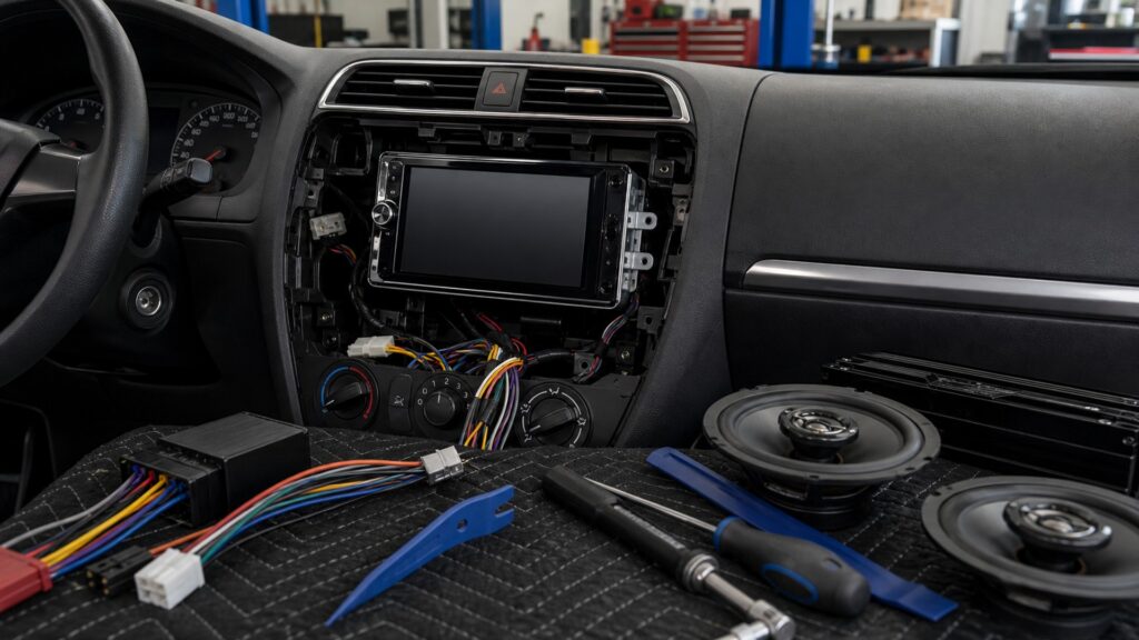
car stereo head units work explainer hero image for Review Streets
What You'll Learn

Follow Four Paths through the Receiver

Power state, source data, user commands, and output signals enter the same chassis through different interfaces; a radio tuner is one source path, while each output leaves toward a different vehicle function.

  • How constant and accessory power establish receiver state
  • How tuners and connected devices supply program material
  • Where decoding turns data into audio channels
  • How controls alter source, level, and routing
  • Why preamp and speaker outputs serve different loads
  • How cameras and microphones use separate paths
  • Where a vehicle interface translates retained functions

Tip: When one feature fails, name its path first; music playback cannot prove that reverse trigger, microphone, data-bus, or amplifier-turn-on wiring is correct.

Definitions

Key Concepts That Define Car Stereo Head Units

These concepts identify the receiver's distinct power, data, control, audio, and accessory interfaces.

Constant Battery Feed

A protected supply that can preserve memory and support defined receiver functions independently of the accessory state.

  • Vehicle procedure controls connection
  • Parasitic draw matters at shutdown
  • It is not the speaker power output

Accessory Wake Signal

A switched voltage or interface command telling the receiver when the vehicle permits normal operation.

  • Some vehicles provide data instead of a simple wire
  • Cranking can change voltage
  • Shutdown timing affects battery drain

Source Transport

The radio, cable, wireless profile, or storage protocol carrying program information into the receiver.

  • Connection does not guarantee supported content
  • Bandwidth and profile affect features
  • Source selection chooses the active path

Audio Decoding

Conversion of supported broadcast or stored data into timed digital samples and then audio channels for processing or output.

  • Formats require compatible decoders
  • Errors can mute or interrupt playback
  • Decoding precedes analog output

Preamplifier Output

A low-level audio signal intended for an external amplifier or processor rather than for driving a passive speaker directly.

  • Voltage range affects gain matching
  • Channel count limits routing
  • Cable and grounding affect noise

Speaker-Level Output

An internally amplified channel intended to drive a supported speaker load through the receiver harness.

  • Power is limited by receiver design
  • Impedance rules still apply
  • Outputs must not be tied together casually

Tip: Trace only one signal at a time from its origin to the corresponding connector or downstream device.

Power State

Constant Supply and Vehicle Wake Logic Start the Sequence

The receiver needs a protected supply and a valid wake condition. Depending on the vehicle, accessory state may arrive as switched voltage or through an interface reading network messages. During cranking and shutdown, voltage and timing determine whether the unit reboots, stores settings, or stays awake unexpectedly.

  • Confirm constant, switched, and ground functions
  • Observe behavior during key and start states
  • Verify delayed-accessory shutdown where equipped
  • Measure off-state draw through approved methods

A receiver that powers up has passed only the first operating stage.

Source Acquisition

The Active Tuner or Connection Delivers Program Data

AM/FM, satellite, USB, Bluetooth, wired phone projection, and wireless projection use different transports and authentication steps. The receiver selects one, validates its supported format or profile, and buffers or decodes data before audio processing begins.

  • Test each source independently
  • Distinguish pairing from media-audio connection
  • Confirm antenna or cable path
  • Use supported files, phones, and settings

A connection icon does not prove that the intended audio stream is active.

Command and Processing

Controls Change State before the Audio Leaves

Buttons, touchscreen events, knobs, steering commands, and voice requests alter source, track, level, balance, crossover, equalization, or call state. The receiver then prepares channels through digital processing and volume control while preserving enough headroom for the selected output path.

  • Separate source volume from receiver volume
  • Configure complex menus while parked
  • Set routing before tonal adjustment
  • Verify calls and prompts at predictable levels

The interface commands the audio path; it is not itself the final acoustic output.

Audio Output

Internal Power and Preamp Signals Feed Different Destinations

A receiver may drive supported speakers with an internal amplifier, send low-level signals to an external amplifier, or do both on assigned channels. Remote-turn-on control wakes downstream equipment, while crossover and level settings must match the wiring actually used.

  • Identify each harness and preout channel
  • Do not connect passive speakers to preouts
  • Match external-amplifier gain to signal level
  • Confirm clean output before diagnosing speakers

Output topology determines the next electrical load and the correct measurement point.

Accessory Coordination

Cameras, Microphones, and Vehicle Interfaces Follow Parallel Routes

A reverse camera uses power, video, and a trigger; a microphone uses a dedicated input and placement; steering controls and retained vehicle features may require programmed interfaces. These parallel paths can succeed or fail independently of ordinary radio playback.

  • Test reverse and camera view behavior
  • Place and test the call microphone
  • Verify steering commands one by one
  • Confirm every retained chime, setting, and screen

Complete operation means each accessory path responds in the vehicle state for which it was designed.

Quick Reality Check

The Receiver Coordinates Many Functions but Does Not Own the Whole Car

A head unit is an upstream hub; downstream amplifiers, speakers, cameras, phones, interfaces, and vehicle modules retain their own limits.

What Receiver Logic Can Control

Source choice, supported decoding, user commands, audio routing, volume, available processing, accessory triggers, and defined display functions originate or converge here.

Systematic path testing can distinguish a receiver setting or output fault from a problem in an attached device or downstream circuit.

What Lies Outside Its Authority

It cannot make an unsupported phone profile compatible, repair a vehicle network, drive an unsafe load, restore a damaged speaker, or improve poor enclosure construction.

Some factory climate, warning, camera, amplifier, and settings functions remain dependent on separate modules and exact integration hardware.

Common Myths

Misconceptions About Car Stereo Head Units

These myths collapse independent power, source, output, and accessory paths into one assumption about the dashboard screen.

If Bluetooth pairs, wireless audio must work

Pairing establishes a relationship, but the required media profile, permissions, active source, phone routing, receiver compatibility, and software state still determine playback. Call audio and music can also use different profiles and level settings.

Preamp outputs can drive speakers directly

Preamp connections provide low-level signals for an external amplifier or processor. Passive speakers require suitable power amplification and a supported load. Connecting them to an unintended output will not create the required current or controlled response.

A working radio proves the receiver wiring is complete

Radio playback can pass while reverse trigger, camera video, microphone, steering controls, amplifier turn-on, USB extension, parking input, illumination, or retained data remains wrong. Each connector and vehicle state needs a separate functional test.

The biggest screen determines how well the head unit works

Screen size affects viewing and packaging, not tuner reception, decoding support, output voltage, amplifier compatibility, microphone quality, startup behavior, retained functions, or software stability. Operation depends on the complete interface and signal architecture.

Tip: Use the working feature only as evidence for its own route; test the failed route from origin to connector.

FAQ

Frequently Asked Questions About Car Stereo Head Units

These answers clarify receiver startup, source handling, outputs, accessory paths, and the boundary between the head unit and downstream equipment.

Why does a head unit have constant and switched power?

Constant supply can preserve memory and support defined functions, while a switched voltage or network-derived command controls normal vehicle-state operation. Exact wiring varies, so the receiver, interface, and vehicle diagrams must identify each circuit.

What happens after a phone sends audio?

The receiver accepts a supported wired or wireless transport, decodes or receives the audio stream, applies routing and level processing, then sends channel signals through its internal amplifier or preamp outputs toward downstream equipment.

What is the remote turn-on wire for?

It provides a control signal that tells compatible external amplifiers or accessories when to operate. It is not their main power supply. Current capability and connection requirements must follow the receiver and downstream product instructions.

Why can calls work when music does not?

Hands-free calling and media playback may use different wireless profiles, source selections, permissions, microphones, volume memories, and routing. Test call audio, call microphone, and media audio separately instead of treating one successful Bluetooth function as complete proof.

How does a head unit display a reversing camera?

The camera needs correct power and video format, while the receiver needs a valid input and reverse-state trigger. It then switches the screen to that input; image presence does not replace direct observation or safe backing practice.

Bottom Line

A car stereo head unit works by coordinating power state, source transport, decoding, user commands, audio processing, output topology, and parallel accessory interfaces.

Trace those routes separately. A receiver can play one source while another source, camera, microphone, vehicle interface, or downstream amplifier fails, so complete verification must reproduce each feature in its intended vehicle state.

Next Steps

Continue from Receiver Operation to Fit and System Scope

These explainers connect the internal sequence to vehicle-specific installation constraints, operating-purpose decisions, and the larger audio chain downstream.

How Car Audio Systems Work

Follow the preamp or speaker outputs into processing, external amplification, loudspeakers, and cabin acoustics.

Quick Summary

Car Stereo Head Units Explained

  • Power state begins with protected supply and a valid wake command.
  • Each tuner or device uses its own source transport.
  • User controls change routing and level before output.
  • Preamp and speaker outputs serve different electrical destinations.
  • Cameras, microphones, and retained controls use parallel paths.