How Single Axle Utility Trailers Work

A single-axle utility trailer carries a load on a deck and frame supported by one axle assembly and, when coupled, the towing connection. The tow vehicle supplies the pulling force. Hubs and bearings let the wheels rotate, tires contact the road, and the coupling allows the vehicle and trailer to change direction relative to each other.

The trailer is more than a platform on wheels. Load position affects how weight is shared between the axle and hitch. Restraints control movement of goods, while lights and any fitted brakes support road operation. Each part has a defined purpose and limits that apply to the complete loaded arrangement.

By: Review Streets Research Lab
Updated: October 7, 2026
Explainer · 8-12 min read
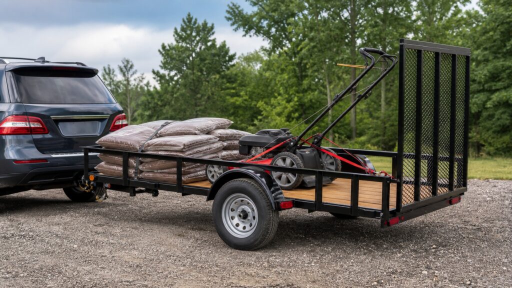
single axle utility trailers explainer hero image for Review Streets
What You'll Learn

Follow the Forces Through the Trailer

Connect the deck, frame, tongue, axle, and road wheels.

  • How the deck and frame support cargo
  • Why some load reaches the hitch
  • How hubs, bearings, and tires allow rolling
  • What the coupling and fitted brakes do
  • Why cargo restraint remains separate from the trailer structure

Tip: Distinguish the load carried by the trailer from the loads imposed on each part of the towing combination.

Definitions

Six Systems Behind a Single-Axle Trailer

These parts perform different jobs in supporting and moving cargo.

Load path

The load path is the route through which cargo forces pass into the supporting structure and its connections.

  • Example: a machine’s weight passing from deck supports into the frame
  • Check: the intended deck and structural loading provisions
  • Limit: deck area alone does not state structural capacity

Tongue load

Tongue load is the downward load applied at the towing connection.

  • Example: moving cargo changing the load at the coupler
  • Check: specified distribution and hitch or vehicle limits
  • Limit: the axle does not carry the entire coupled trailer load

Axle assembly

The axle assembly supports the wheel ends and carries loads through its designed attachments.

  • Example: one axle beneath the utility deck
  • Check: the exact axle and trailer ratings
  • Limit: an axle rating alone is not the whole trailer’s cargo rating

Hub bearing

A hub bearing supports rotation at the wheel end.

  • Example: a wheel turning on its supported hub
  • Check: the particular bearing and service arrangement
  • Limit: the bearing still needs appropriate care without an engine

Coupling articulation

Coupling articulation allows permitted relative movement between the towing vehicle and trailer.

  • Example: the trailer changing angle behind the vehicle in a turn
  • Check: the coupling’s movement limits and clearances
  • Limit: a coupling does not allow unlimited angles

Load restraint

Load restraint controls cargo movement relative to the trailer.

  • Example: a machine secured to suitable attachment points
  • Check: cargo and restraint instructions
  • Limit: a frame supports weight but does not automatically secure loose goods

Tip: Support, rotation, connection, and restraint are separate functions that must cooperate.

Support

The Deck Transfers the Load into the Frame

The cargo rests on the intended load-carrying surface. Deck supports and frame members transfer that load toward the axle support and tongue. Concentrated loads, such as machine wheels, can place demands on particular areas, so the trailer’s intended loading provisions matter. Rails and gates have their own functions and should not be treated as unlimited supports.

  • Use the intended load-bearing surface.
  • Respect the exact deck and ramp provisions.
  • Check the completed trailer’s ratings.

A machine can fit within the outer rails while imposing a load the deck or ramp was not designed to support. Geometric fit and structural suitability answer different questions.

Distribution

The Axle and Hitch Share the Coupled Load

A conventional coupled utility trailer places part of its load on the tow vehicle through the tongue and hitch. Cargo location changes that share. Moving a heavy object rearward or forward can alter tongue load without changing total mass. Follow the specified distribution and check relevant axle, hitch, and vehicle limits.

  • Include the trailer’s own mass and equipment.
  • Use the required load-placement guidance.
  • Reassess distribution after partial unloading.

Carry-On’s manual distinguishes gross trailer weight from axle loading because some load is supported by the tow vehicle. That is why simply comparing cargo weight with an axle rating is incomplete.

Reference: Carry-On trailer and axle loading explanation.

Rolling

Hubs and Bearings Let the Wheels Turn Under Load

The hub and bearing arrangement supports rotating wheels at the axle ends. Tires provide contact with the road. Suspension, where fitted, permits controlled movement between the axle and supporting structure; exact arrangements differ. These components carry loads while moving, which is why tire condition, wheel attachment, bearings, and suspension need appropriate inspection and service.

  • Identify the actual running-gear design.
  • Use the specified tires and inflation guidance.
  • Maintain wheel ends by their own instructions.

Dexter’s service manual covers different axle and wheel-end arrangements. The shared purpose is rolling support, but bearing procedures and service details cannot be assumed identical across trailers.

Reference: Dexter axle and wheel-end instructions.

Towing and stopping

The Connection Transfers Pulling Force and Allows Movement

The towing vehicle pulls through the hitch and coupler into the trailer tongue and frame. The connection permits specified relative movement for turning and road transitions. Lights communicate with other road users, and trailers equipped with brakes use their particular braking system to contribute to stopping. Any fitted breakaway system has a separate emergency role.

  • Use compatible connection equipment.
  • Keep articulation clear of interference.
  • Operate fitted braking and electrical systems as specified.

A plug, coupler, and safety connections are parts of a supported combination. Their presence does not by itself prove correct engagement, wiring, or brake operation.

Cargo control

Restraints Keep the Load with the Moving Trailer

When the combination brakes, turns, or crosses a bump, loose cargo can move relative to the deck. Appropriate restraints and attachment points control that movement; suitable containment prevents loose material escaping. A raised gate or side rail is not automatically a substitute for the cargo’s required securement. Equipment moved or removed during a trip changes the arrangement.

  • Use restraint suited to the actual goods.
  • Keep attachment points accessible and serviceable.
  • Check remaining cargo after load changes.

NHTSA’s load-security guidance highlights sudden braking, bumps, and escaping objects. A trailer’s ability to support an object while parked does not establish that the object will remain controlled during travel.

Reference: NHTSA load-security guidance.

Quick Reality Check

Supporting Weight and Controlling a Load

The trailer structure and cargo restraint solve related but different problems.

Support and movement

Deck and frame transfer load to the axle and towing connection.

Wheel ends and tires let the supported trailer roll.

Control during travel

Compatible connections and fitted systems support the towing operation.

Appropriate restraint limits cargo movement and escape.

Common Myths

Misconceptions About Single-Axle Trailer Mechanics

Avoid assigning every function to the axle or deck.

The axle carries the entire coupled load

Some load is transferred to the towing vehicle through the tongue and hitch.

The axle rating is the cargo capacity

Trailer mass and all applicable design and combination limits still count.

A trailer without an engine needs little care

Tires, bearings, attachment hardware, structure, and fitted systems still require maintenance.

A gate that stays closed secures all cargo

Goods need suitable restraint for the forces and movement of travel.

Tip: Understand what each part does before using its rating as evidence for a different function.

FAQ

Questions About How Single-Axle Utility Trailers Work

Answers about support, rolling, connection, and restraint.

What makes the trailer move?

The tow vehicle supplies pulling force through the connection, tongue, and frame while the trailer wheels roll.

Why does cargo location matter?

It changes load distribution, including tongue load, even if the total mass is unchanged.

Do all single-axle trailers use the same suspension?

No. Identify the actual axle and suspension arrangement and follow its instructions.

Do they all have brakes?

No single configuration follows from axle count alone. Check the trailer’s equipment and applicable requirements.

Why are tie-downs needed on a walled trailer?

Walls and gates do not automatically provide the restraint required for every load and operating condition.

Bottom Line

A single-axle utility trailer works through a connected load path: deck and frame, axle and wheels, and tongue and hitch.

Correct distribution, suitable restraint, and serviceable fitted systems let that structure perform its intended hauling role.

Next Steps

Go Deeper or Compare Your Options

Use these Review Streets paths to compare related categories and practical next decisions.