
Electronic Control Unit
A module containing power conditioning, computing, memory, inputs, outputs, and communications for assigned functions.
- May host several features
- Depends on software and coding
- Failure can be local or network-wide
Car electronics and driving technology work as layered information-and-control systems. Electrical power wakes modules; sensors translate speed, position, temperature, pressure, light, sound, and images into signals; networks share selected data; software compares inputs with rules; outputs inform the driver or command an actuator.
The chain is distributed rather than controlled by one master computer. A camera may identify lane markings while radar estimates range, a brake module knows wheel speed, and a display reports the result. Timing, calibration, voltage, network health, and software version can therefore matter as much as the sensor itself. Assistance remains bounded by weather, visibility, road geometry, maintenance, and the driver's responsibility to monitor the vehicle.
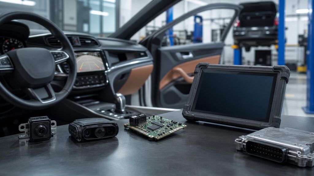
The system becomes understandable when every feature is traced through power, sensing, communication, decision logic, output, and feedback.
Tip: When troubleshooting a feature, draw the chain from power and ground to input, network message, decision condition, output, and final physical response before replacing any module.
These terms describe the shared architecture behind infotainment, diagnostics, cameras, driver assistance, and convenience features.
A module containing power conditioning, computing, memory, inputs, outputs, and communications for assigned functions.
Electrical or digital information representing a measured physical condition.
A shared vehicle network that lets multiple modules transmit prioritized messages over common wiring.
A device that converts an electrical command into motion, pressure, light, sound, heat, or another physical output.
Stored parameters that align sensor position, vehicle configuration, or control behavior with a known reference.
Displays, sounds, controls, haptics, and menus through which the system communicates with the driver.
Tip: A feature name is the user-facing result; service information is needed to identify the exact modules, messages, and conditions that produce it on one vehicle.
Modules need voltage within a defined range, low-resistance grounds, protected feeds, and correct ignition or network wake states. Cranking dips, corrosion, or poor ground paths can create intermittent faults across unrelated-looking features.
Digital symptoms often begin with analog power integrity.
Each sensor measures a limited physical property within a field, range, and update rate. Software combines those measurements and checks whether values agree, but dirt, obstruction, alignment, weather, or bias can reduce useful perception.
A sensor reports evidence about the world, not a complete understanding of it.
Modules publish speed, status, requests, and fault information on networks such as CAN. Feature software uses those messages, local inputs, configuration, and timing rules to decide whether to operate, warn, inhibit, or record a fault.
The module that reports a problem may only be missing information created somewhere else.
A result can appear as a display, tone, steering-wheel vibration, camera image, motor movement, throttle request, steering assistance, or brake pressure. Safety-related systems often arbitrate commands and permit driver override within designed limits.
A message on the screen and an action at the wheels are different outputs with different verification needs.
Modules monitor circuits, message timing, rationality, and some actuator response, then store codes or snapshots. Repair may require wiring correction, component work, coding, calibration, software, and a controlled verification drive.
Stored diagnostics narrow the investigation; only restored behavior proves the system works again.
Electronics can sense, calculate, communicate, and act quickly while remaining dependent on power, calibration, environment, and driver understanding.
Shared sensors and networks let braking, powertrain, body, navigation, camera, and driver-assistance systems coordinate information without duplicating every input.
Diagnostics and software can detect implausible signals, inhibit unsafe operation, preserve fault context, and support more targeted repair.
A warning-free dashboard cannot prove every sensor sees correctly, every feature is calibrated, or every edge case is safe.
Driver-assistance features vary by vehicle and remain limited by visibility, weather, markings, object detection, maps, software assumptions, maintenance, and human attention.
Electronics myths often assign intelligence to a single module or treat a code, warning, or software update as a complete diagnosis.
Modern vehicles use many specialized modules connected by several networks. A feature may span power, camera, radar, brake, steering, body, and display modules, so one symptom does not identify one failed computer.
A code identifies a monitored condition or circuit context. Wiring resistance, voltage, contamination, mechanical failure, missing network data, calibration, software, or the named component can each produce the recorded condition.
Current consumer systems may warn or assist with braking, steering, or speed while the driver remains responsible for monitoring and control. Feature names and capabilities vary, so the owner's manual governs use.
Updates can correct documented logic or compatibility issues, but they cannot repair poor power, corrosion, damaged wiring, blocked sensors, mechanical faults, or incorrect installation. Diagnosis must establish whether software is relevant.
Tip: Trace the whole signal-and-control chain and respect the feature's published operating boundary.
These answers address battery replacement, sensor cleaning, calibrations, aftermarket accessories, and why one fault can disable several features.
Low or unstable voltage can reset modules, distort references, interrupt messages, and create wake-up faults during starting. Test battery, charging, power, and grounds under the conditions that reproduce the complaint.
Accessible covers or lenses may be cleaned using vehicle guidance, but avoid abrasive products, coatings, pressure damage, or moving the sensor. Persistent warnings after cleaning need service information and calibration assessment.
Requirements vary after sensor replacement, windshield work, collision repair, alignment, ride-height change, tire changes, or module programming. Use the exact vehicle procedure; successful calibration should be followed by appropriate functional verification.
Poor power taps, grounds, network adapters, radio-frequency emissions, blocked sensor views, and software permissions can create faults or battery drain. Install with documented interfaces, proper protection, and an easily reversible configuration.
Several features may depend on the same measurement or network message. When confidence falls, modules can inhibit dependent functions rather than act on uncertain data, creating a cluster of warnings from one upstream problem.
Car electronics and driving technology work by converting physical conditions and driver requests into signals, sharing them across modules, applying software logic, and returning information or controlled action.
Reliable operation requires stable power, plausible sensing, intact networks, correct calibration, secure current software, clear interfaces, and physical verification. Convenience and assistance remain systems, not magic or substitutes for attentive driving.
Continue with dash-camera recording and OBD-II monitoring to see how two familiar technologies collect, preserve, and interpret different forms of vehicle evidence.
Trace image capture, loop storage, incident protection, metadata, and privacy in a dedicated recording system.
Follow emissions monitoring from self-test through code storage, scan data, diagnosis, and readiness verification.
See how electronic control overlays a hydraulic and friction braking chain without exceeding tire-road grip.
Choose a retailer
Prices checked regularly. We may earn a commission at no cost to you.