
Electric Vehicle Supply Equipment
Equipment that manages safe delivery of electrical energy from a site to an electric vehicle.
- It signals available current
- Contactors isolate power until conditions are met
- It is often called a charger informally
EV charging works as a negotiated energy-transfer system, not as an extension cord connected directly to battery cells. The site supplies protected electrical power; electric vehicle supply equipment advertises available current and controls contactors; the vehicle confirms connection and requests energy; onboard electronics convert and manage power while the battery system monitors voltage, temperature, and state of charge.
The path changes with charging type. During AC charging, the vehicle's onboard charger converts alternating current to battery-compatible direct current. During DC fast charging, station equipment performs the conversion and feeds controlled DC through a compatible inlet. Connectors, adapters, cables, portable cordsets, mounts, and software must all match the vehicle, site, rating, environment, and network access.
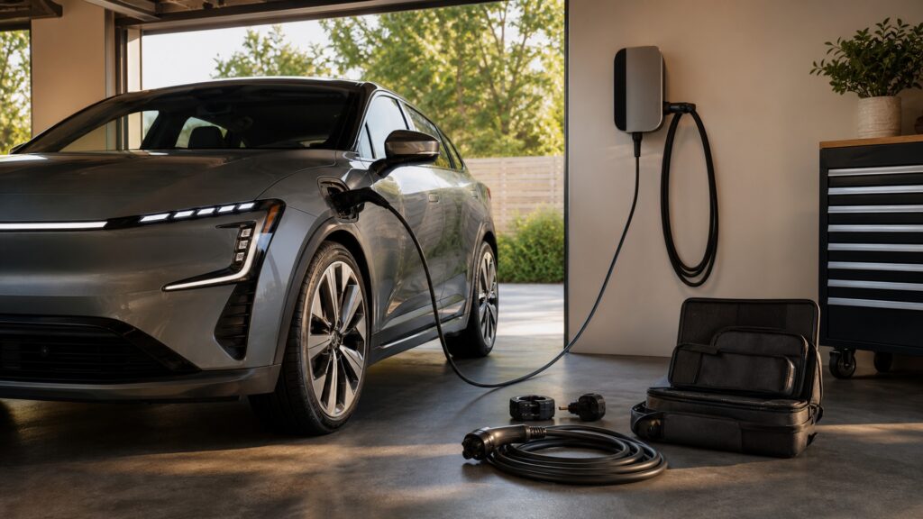
The complete mechanism includes site capacity, circuit protection, signaling, contactor closure, conversion, battery acceptance, thermal control, billing or access, and safe disconnection.
Tip: When charging fails, record the site, connector, displayed limit, vehicle state of charge, battery temperature, error message, and a second known-good location before replacing equipment.
These terms assign each charging function to the correct side of the connection.
Equipment that manages safe delivery of electrical energy from a site to an electric vehicle.
A signaling path used by compatible conductive charging systems to communicate connection and allowable current states.
Vehicle power electronics that convert incoming AC into controlled DC for the traction battery.
Charging in which off-board equipment supplies controlled direct current to the vehicle battery interface.
Vehicle electronics that monitor cells and constrain charging to protect the battery system.
A device that creates a physical and electrical interface between otherwise different compatible charging connections.
Tip: Power advertised by a station is only an upper bound; circuit capacity, vehicle conversion, battery temperature, state of charge, and software can all set lower limits.
A dedicated circuit, overcurrent protection, wiring, disconnects where required, and rated EVSE form the site side. Before energizing the cable, the EVSE detects a valid connection, advertises capability, checks required safety conditions, and closes internal contactors.
The wall unit controls access to site power; it does not decide how quickly every battery can accept energy.
With AC supply, the vehicle's onboard charger rectifies and regulates incoming energy before the battery. Delivered power cannot exceed the weakest relevant limit among circuit, EVSE, cable, connector, onboard charger, battery request, and thermal conditions.
A higher-rated EVSE does not force extra current into a vehicle whose onboard system requests less.
A fast-charging station converts grid power to DC and communicates closely with the vehicle before applying it to the high-voltage battery path. The vehicle continually specifies acceptable voltage and current as cells warm and state of charge rises.
The station supplies capability, while the vehicle's battery system controls what the pack will accept at each moment.
Battery chemistry, cell voltage, temperature, state of charge, thermal-system capacity, pack architecture, charger sharing, and protective limits shape a charge curve. Cold or hot packs and high state of charge commonly reduce accepted power even at a capable station.
Peak power is a brief capability point; trip time depends on the useful area under the entire charging curve.
Portable EVSE adds plug, receptacle, cable, temperature, and storage interfaces. Adapters add mating and rating limits. Apps and accounts can govern initiation or payment. Cable hangers and bollards prevent damage but must preserve connector cleanliness and accessibility.
Physical fit is only one layer of compatibility; power rating, signaling, authorization, and safe mechanical support must also align.
Charging succeeds only when the site, equipment, connector, vehicle, battery, thermal system, and access service agree on a safe operating point.
AC equipment can turn parking time into routine energy replenishment, while DC fast charging supports higher-power travel stops by moving conversion off the vehicle.
Standards and listed equipment can coordinate signaling, interlocks, current limits, and connector behavior across many vehicles and sites.
A matching plug does not guarantee protocol support, authorization, adapter approval, station uptime, cable reach, or the advertised charging power.
Battery temperature, state of charge, onboard conversion, site sharing, and protective limits can reduce power without indicating a defective vehicle or station.
These myths confuse electrical capability with commanded energy transfer.
Compatible EVSE communicates the maximum available current, while the vehicle requests within that limit. The onboard charger, battery controls, temperature, and state of charge can choose substantially less than the equipment rating.
During AC charging, conversion to battery-compatible DC occurs in the vehicle's onboard charger. During DC fast charging, off-board power electronics perform that conversion and the vehicle manages permitted battery voltage and current.
Adapters have defined connector pairs, voltage, current, temperature, locking, and communication requirements. The vehicle or network may restrict their use, and an unqualified device can overheat or defeat intended mechanical and electrical safeguards.
A vehicle may reach peak briefly before tapering, or never reach it because of temperature, state of charge, shared equipment, or battery limits. Energy delivered across the complete curve determines elapsed charging time.
Tip: Follow who advertises, converts, requests, limits, and records power before drawing a conclusion from a connector or peak number.
These answers cover rain, extension cords, charging losses, connector inspection, and how to diagnose a slow session.
Properly installed, listed outdoor-rated equipment is designed for outdoor charging and uses interlocks before energizing. Do not use damaged, submerged, contaminated, improvised, or incorrectly rated equipment, and follow the vehicle and EVSE instructions.
Do not unless the vehicle and charging-equipment manufacturer expressly allow a specified solution. Extra connections add resistance, heat, water exposure, voltage drop, damage, and rating uncertainty during a long continuous electrical load.
Conversion, cable resistance, battery heating or cooling, pumps, electronics, and cell balancing consume energy. Losses vary with power level, temperature, equipment efficiency, battery condition, and how the vehicle reports usable battery energy.
Stop for bent, recessed, corroded, wet, contaminated, cracked, melted, discolored, loose, or unusually hot pins, latches, cables, plugs, or receptacles. De-energize safely and obtain qualified inspection rather than forcing a connection.
Record supplied voltage and current limit, vehicle request, state of charge, battery temperature, preconditioning, station sharing, cabin loads, errors, and energy over time. Compare another compatible site before assigning the fault.
EV charging works by negotiating safe power across a site circuit, EVSE, connector, vehicle conversion path, battery controls, and thermal system.
Select gear by the weakest real interface, protect every connection, verify signaling and access, and judge performance by energy delivered across the session rather than a label or peak display.
These explainers develop the three decisions owners meet most often: Level 2 capacity, home installation, and the NACS-versus-CCS interface.
See how 208- or 240-volt AC charging converts dwell time and circuit capacity into routine replenishment.
Plan the service assessment, location, cable route, utility schedule, and daily energy workflow for residential charging.
Compare SAE J3400 NACS with CCS by contact layout, AC and DC paths, communication, adapters, network access, and transition risk.
Choose a retailer
Prices checked regularly. We may earn a commission at no cost to you.