What Makes NACS Different from CCS

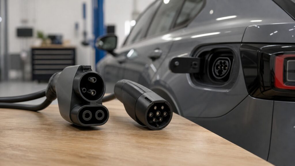
NACS and CCS are charging interfaces, not complete charging networks. SAE J3400, commonly called the North American Charging System, uses one compact coupler whose two main current-carrying contacts support either single-phase AC or DC operation. North American CCS1 builds DC fast-charging contacts beneath the established SAE J1772 AC interface, creating a larger combo inlet.

The physical difference affects handling and vehicle packaging, but it does not decide every charging experience. Communication, voltage, current, cable cooling, station reliability, account access, payment, vehicle authorization, adapter approval, and software support still govern a session. During the market transition, owners must identify the vehicle inlet, native AC path, native DC path, available qualified adapters, and specific networks rather than relying on a logo.

By: Review Streets Research Lab
Updated: August 26, 2026
Explainer · 8-12 min read
nacs different from ccs explainer hero image for Review Streets
What You'll Learn

Separate Connector Geometry from Charging Capability and Network Access

The comparison follows contact assignment, mating, AC and DC paths, signaling, adapters, vehicle software, and station authorization without treating the plug as the entire ecosystem.

  • How J3400 shares main contacts between AC and DC
  • Why CCS adds DC pins to the J1772 outline
  • Where control and communication still matter
  • How adapters preserve or limit interfaces
  • Why station access differs from physical fit
  • What owners should verify during the transition

Tip: Build a vehicle-specific compatibility card listing native inlet, supported AC connector, supported DC connector, approved adapters, maximum ratings, and enabled networks before a road trip.

Definitions

Key Concepts That Define NACS and CCS Charging Interfaces

These terms distinguish standards, physical couplers, charging modes, and commercial access.

SAE J3400

A North American conductive charging standard covering physical, electrical, functional, safety, and performance requirements for its coupler.

  • It supports AC or DC on shared contacts
  • It developed from the Tesla connector
  • The standard continues to evolve

North American Charging System

The common name NACS used for the connector system standardized through SAE J3400.

  • Name and network are separate
  • Vehicle implementations vary
  • Adapters require defined qualification

SAE J1772

The established North American conductive charging architecture and coupler used for AC charging and as the upper portion of CCS1.

  • It defines functional requirements
  • Control contacts coordinate connection
  • Revisions matter

CCS1

The North American Combined Charging System inlet combining the J1772 AC interface with two additional large DC contacts.

  • AC uses the upper contacts
  • DC uses the combo arrangement
  • Vehicle support is implementation-specific

Shared Power Contacts

J3400's use of the same two primary current contacts for either AC or DC in different charging states.

  • Interlocks prevent unsafe switching
  • Vehicle contactors route the path
  • Control logic is essential

Qualified Adapter

An adapter evaluated for a defined vehicle, connector pair, power direction, mechanical lock, communication, voltage, current, and temperature use.

  • Approval is not universal
  • Ratings can differ by mode
  • Software authorization may remain necessary

Tip: Use the current vehicle and charging-provider documentation; adoption announcements and connector shape do not prove that a particular car can initiate a particular station today.

Contact Architecture

How J3400 and CCS1 Route AC and DC through Different Physical Layouts

J3400 uses its two main contacts for single-phase AC or DC, with the vehicle configuring the internal path after negotiation. CCS1 retains J1772 contacts for AC and adds separate large DC contacts below for fast charging.

  • Identify which contacts carry each mode
  • Inspect latches and seals
  • Never force a mismatched coupler
  • Treat damaged inlets as safety faults

The compactness difference comes from contact architecture, not from removing the need for isolation, signaling, or power electronics.

Handling and Packaging

Why Size, Mass, Cable Design, and Port Location Affect Daily Use

J3400's smaller mating face can be easier to handle and package. CCS cable assemblies may feel larger, especially at high power, yet cable cooling, length, stiffness, temperature, station holster, and vehicle inlet location can dominate the real effort.

  • Test reach from realistic parking positions
  • Support heavy cables during alignment
  • Keep pins clean and dry
  • Avoid twisting or hanging load from the inlet

Connector family influences ergonomics, but the installed cable and parking geometry determine the session in hand.

Communication and Access

Why a Matching Coupler May Still Refuse to Charge

Before power flows, vehicle and equipment coordinate connection state, permitted energy, safety checks, and sometimes higher-level communication. Networks can also require account eligibility, payment, station activation, or vehicle software support beyond the physical interface.

  • Confirm vehicle firmware and enrollment
  • Check station and adapter eligibility
  • Carry a payment fallback
  • Read the exact failure message

Physical compatibility is necessary but can remain insufficient when protocol, authorization, or commercial access is missing.

Adapters and Transition

How an Extra Interface Changes Rating, Locking, Temperature, and Responsibility

A qualified adapter can connect selected J3400 and J1772/CCS equipment, but it adds two mating surfaces, thermal monitoring questions, mechanical retention, storage, and vehicle-specific approval. SAE J3400/1 addresses evaluation for defined adapter use.

  • Use only vehicle-approved adapter paths
  • Respect separate AC and DC ratings
  • Support and lock the assembly fully
  • Inspect both interfaces after high-power sessions

An adapter bridges specified interfaces; it does not make every charger, vehicle, voltage, or network interchangeable.

Ownership Decision

What to Verify beyond the Connector during a Multi-Year Transition

A buyer should map home AC equipment, workplace access, common travel corridors, station reliability, adapter timing, vehicle software, charging curves, and service support. Future standard adoption does not erase the installed base or guarantee equal access.

  • Audit routes rather than national totals
  • Separate native and adapted charging
  • Verify delivery dates and included hardware
  • Keep multiple working backup locations

The better interface is the one supported by the vehicle, places, and services the owner can actually use.

Quick Reality Check

Different Physical Architectures inside a Larger Interoperability Problem

J3400 and CCS1 package AC and DC contacts differently, while communication, ratings, networks, and vehicle support still decide usable charging.

J3400 Characteristics

A compact coupler uses the same main contacts for AC or DC, potentially simplifying vehicle packaging and everyday connector handling.

SAE standardization creates a public framework for physical, electrical, functional, safety, and performance requirements beyond a proprietary shape.

CCS1 Characteristics and Shared Limits

CCS1 preserves the established J1772 AC interface and adds dedicated DC contacts, supporting a large installed base of vehicles and equipment.

Neither connector guarantees station uptime, maximum power, route coverage, easy cable reach, payment access, or an adapter path for every vehicle.

Common Myths

Misconceptions About NACS and CCS Charging Interfaces

These myths treat connector adoption as instant universal interoperability.

NACS and the Tesla Supercharger network are the same thing

NACS describes a connector system standardized as SAE J3400; a charging network is equipment, sites, software, access, and operations. A J3400 inlet does not by itself guarantee access to every Supercharger location.

CCS cannot charge with AC power

A CCS1 vehicle inlet includes the SAE J1772 AC interface above the added DC contacts. Compatible Level 1 or Level 2 charging uses the J1772 portion, while DC fast charging uses the combo connection.

An adapter gives every EV the same charging speed

Adapters have ratings, while vehicle voltage, charge curve, battery temperature, station power, cable cooling, state of charge, and network limits remain. Translation of the connector cannot raise the weakest capability elsewhere.

Automaker adoption makes older connectors immediately obsolete

Vehicles and stations remain in service for years, and adapters or mixed-cable sites can extend usefulness. Transition pace differs by manufacturer, vehicle, network, home installation, region, and supported charging mode.

Tip: Separate what the coupler standard defines from what the vehicle, station, network, software, and commercial arrangement enable.

FAQ

Frequently Asked Questions About NACS and CCS Charging Interfaces

These answers address home charging, adapters, network access, voltage, and how to evaluate a vehicle during the transition.

Can a J3400 vehicle use a J1772 home charger?

Many can through a vehicle-supported J1772-to-J3400 AC adapter, but approval, current rating, locking, and included hardware vary. Follow the exact vehicle and equipment instructions rather than assuming every physical adapter is suitable.

Can a CCS1 vehicle use a J3400 fast charger?

Only when the vehicle, charging provider, software, site, and qualified DC adapter path all support it. Some deployments offer native CCS cables or station-provided adapters, while others remain inaccessible to that vehicle.

Does J3400 support both AC and DC charging?

Yes. SAE J3400 covers a hand-mated coupler capable of transferring either single-phase AC or DC through the two primary current contacts, with control and vehicle switching determining the operating mode.

Which connector supports higher voltage or power?

Do not infer practical power from shape alone. Standard revisions, vehicle architecture, cable and contact thermal design, station output, adapter limits, and battery acceptance determine the supported voltage and delivered charging curve.

What should a new-EV buyer compare?

Compare native inlet, included adapters, home equipment, AC acceptance, DC curve, route-specific stations, reliability, account access, cable reach, software support, adapter delivery, maintenance, warranty, and usable alternatives near frequent destinations.

Bottom Line

NACS and CCS differ most visibly in contact architecture: SAE J3400 shares primary contacts between AC and DC, while CCS1 adds dedicated DC contacts beneath the J1772 AC interface.

That geometry does not settle charging access; verify signaling, ratings, adapters, vehicle software, station networks, route coverage, and actual session performance.

Next Steps

Place the Connector inside the Full Charging and Home Systems

These explainers connect physical interface choice to energy flow, Level 2 capacity, and the equipment an owner will use most often.

Why Level 2 Charging Matters

Understand how either supported interface delivers Level 2 AC power within circuit and onboard-charger limits.

Why Home EV Charging Matters

Plan the home equipment, cable, parking, schedule, and fallback decisions that persist through a connector transition.