How OBD Diagnostic Tools Work

An OBD diagnostic tool is a translator and measurement interface. It connects through the vehicle data link, identifies a supported communication path, sends defined requests, receives messages from electronic control modules, and turns coded bytes into names, values, status flags, or graphs. Different functions expose different slices of vehicle state.

The useful output is not a verdict. Trouble codes identify monitored conditions, freeze-frame records preserve a narrow operating snapshot, readiness flags report whether certain self-tests have run, and live parameters show selected values over time. Diagnosis begins when those artifacts are checked against wiring, service information, physical measurements, operating conditions, and a repeatable test.

By: Review Streets Research Lab
Updated: September 8, 2026
Explainer · 8-12 min read
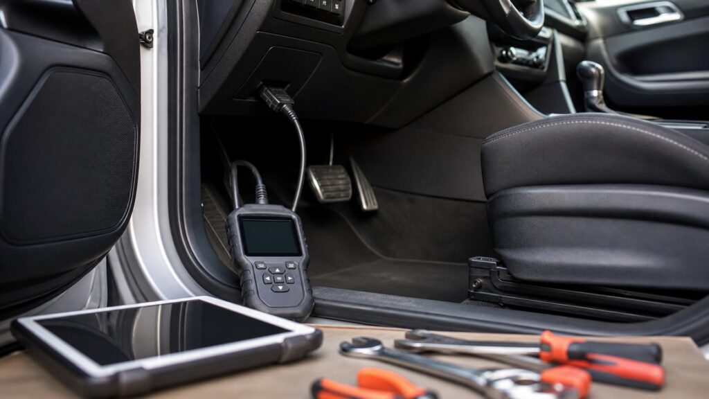
obd diagnostic tools work explainer hero image for Review Streets
What You'll Learn

Trace the Diagnostic Conversation from Connector to Confirmed Repair

The complete mechanism includes electrical access, protocol negotiation, addressed requests, decoding, context preservation, comparison, and controlled verification.

  • How the connector supplies a communication boundary
  • Why a tool must speak a supported protocol
  • What trouble codes actually identify
  • How freeze-frame and readiness differ
  • Why live data needs context and units
  • When active tests add risk
  • What confirms a diagnostic hypothesis

Tip: Save the original evidence before clearing, commanding, unplugging, or changing anything; the first capture often contains the strongest fault context.

Definitions

Key Concepts That Define OBD Diagnostic Tool Mechanism

These six terms describe different evidence types and should never be collapsed into a single code-reading result.

Data Link Connector

The standardized physical vehicle interface used by external diagnostic equipment, with location, contact allocation, and electrical requirements defined for regulated OBD access.

  • Physical fit is only first
  • Pins carry distinct roles
  • Damage can block communication

Diagnostic Trouble Code

An alphanumeric identifier stored when a monitored condition meets fault-setting logic; it points toward a system and condition rather than naming a guaranteed failed part.

  • Status bits add meaning
  • Definitions can be generic or specific
  • Context guides testing

Parameter Identifier

A defined request and response interpretation for a particular item of current or recorded diagnostic data.

  • Support varies
  • Scaling creates units
  • Update rate affects graphs

Freeze Frame

A stored snapshot of selected operating data associated with a fault event under supported OBD behavior.

  • It is not a full log
  • One frame can dominate
  • Preserve it before clearing

Readiness Monitor

A status showing whether a specified onboard emissions self-test has completed since relevant reset conditions, not whether every component is healthy.

  • Not ready differs from failed
  • Drive conditions matter
  • Clearing resets status

Bidirectional Test

A supported command through which a tool asks a module to activate an output, change a state, or run a routine for diagnosis.

  • Capability is vehicle-specific
  • Motion may occur
  • Authorization can be required

Tip: Name the request, vehicle state, units, and module whenever a displayed value matters.

Physical Session

The Connector and Electrical State Establish the First Boundary

The tool needs a compatible connector, correct pin condition, suitable voltage, and a vehicle state that permits communication. A plug that enters the socket can still meet damaged terminals, missing power, poor ground, or an asleep network.

  • Inspect without spreading terminals
  • Verify tool and vehicle voltage needs
  • Select the required ignition state

Physical connection enables a session but does not identify a fault.

Protocol Exchange

Requests Must Reach the Intended Module and Return Intact

After detecting or selecting a protocol, the tool addresses requests and waits for responses. Gateways, module wake-up, network load, security access, and tool coverage influence what appears, while silence has several possible causes.

  • Record protocol and module identity
  • Distinguish unsupported from offline
  • Watch for communication faults

No response is an observation requiring isolation, not proof of a dead controller.

Data Interpretation

Bytes Become Codes, Values, Units, and Status through Definitions

Software applies message definitions, scaling, signedness, units, code libraries, and status meanings. Generic OBD covers regulated emissions information; enhanced functions may expose other modules and manufacturer-specific routines.

  • Confirm unit and data source
  • Separate generic from enhanced coverage
  • Check code status and module

A polished label is only as reliable as the definition and message beneath it.

Context Capture

Stored and Live Artifacts Answer Different Diagnostic Questions

Codes show recognized conditions, freeze frame samples an event, readiness describes completed self-tests, and live data shows requested values during the present test. Combining them reconstructs when a symptom appears and which variables move together.

  • Save a full pre-clear report
  • Graph related values together
  • Reproduce the operating condition safely

Evidence gains meaning when time, load, temperature, and state remain attached.

Hypothesis Test

Diagnosis Compares Electronic Evidence with an Independent Check

A technician turns the evidence into a cause hypothesis, consults the correct service procedure, and checks power, ground, signal, leakage, pressure, motion, or another physical quantity. Repair is confirmed by repeatable operation and monitor behavior.

  • Test before replacing parts
  • Use active commands cautiously
  • Confirm the original condition is gone

The tool narrows the search; disciplined verification closes it.

Quick Reality Check

A Trouble Code Is Evidence, Not a Parts Order

One monitored condition can be produced by wiring, connectors, leaks, shared power, mechanical faults, software, sensor bias, or the named component itself.

What Scan Data Does Well

It exposes module observations, status, timing, and relationships that would otherwise remain hidden.

Saved reports make before-and-after comparisons possible.

What Still Requires Diagnosis

The vehicle usually cannot observe every physical cause directly.

Tool descriptions, databases, and automated suggestions require confirmation against vehicle-specific information and measurements.

Common Myths

Misconceptions About OBD Diagnostic Tool Mechanism

These myths confuse access to controller data with certainty about the physical cause.

The code tells you exactly which part to replace

A diagnostic trouble code identifies a monitored area and operating context, not a guaranteed failed component. Wiring, power, ground, leaks, mechanical behavior, shared inputs, software, or another module can produce the same stored code.

No codes means the vehicle has no fault

Some failures are outside monitored thresholds, intermittent without capture, mechanical, network-specific, or unsupported by the tool. Symptoms, readiness, pending history, live data, physical inspection, and vehicle-specific tests still matter when the code list is empty.

Clearing codes is a repair

Clearing removes diagnostic information and commonly resets readiness state; it does not correct the underlying condition. Preserve the report first, perform a supported repair, then verify recurrence, live behavior, and required self-test completion.

Every scan tool shows the same information

Generic emissions access is standardized in important ways, but module coverage, enhanced data, definitions, update rates, graphing, active tests, topology, coding, security access, and service functions differ by vehicle, tool, software, and license.

Tip: Keep every conclusion proportional to what the vehicle actually measured.

FAQ

Frequently Asked Questions About OBD Diagnostic Tool Mechanism

These answers clarify connection, code status, live values, freeze frame, clearing, and proof after repair.

What should be captured before any codes are cleared?

Save every module's codes and status, freeze-frame records, readiness flags, relevant live values, vehicle identification, voltage, mileage, date, and symptom conditions. Preserve screenshots or reports so the original state remains available after testing.

Why can a tool power up but fail to communicate?

Connector power can be present while communication pins, grounds, protocol selection, gateway routing, module wake-up, network wiring, vehicle state, tool software, or vehicle coverage prevents a valid response. Diagnose the session layer by layer.

How should live data be interpreted?

Confirm the module, parameter definition, units, scaling, update rate, and current operating state. Compare related values and expected physical behavior, then use an independent measurement when a decisive conclusion depends on sensor accuracy.

What does a not-ready monitor mean?

It means the applicable self-test has not completed since a relevant reset or clearing event. It is not the same as a failed monitor, and required enabling conditions may take particular driving and temperatures.

What confirms that a repair succeeded?

Reproduce the original operating condition, verify the symptom and causal measurement changed as predicted, rescan all relevant modules, confirm no returning faults, and allow applicable monitors or service procedures to validate the result.

Bottom Line

OBD tools work by establishing electrical and protocol access, requesting defined records, decoding module responses, and preserving codes, freeze frame, readiness, and live data as separate evidence.

Their output becomes diagnosis only after a hypothesis survives vehicle-specific checks and an independent measurement. Capture first, command cautiously, repair the demonstrated cause, and verify under the conditions that originally exposed it.

Next Steps

Extend the OBD Exchange into Fit, Operation, and Safety

The next explainers apply the data path to tool coverage, state-based testing, vehicle protection, and ongoing reliability.