
Microwave Antenna
The structure that couples incident radio-frequency energy into the detector's receiver path.
- Orientation affects sensitivity
- Obstructions can attenuate signals
- Direction may use multiple elements
A radar detector is a wide-area radio receiver tuned to frequency regions used by speed-measurement radar and other emitters. Its antenna collects weak microwave energy, a receiver front end selects and amplifies portions of the spectrum, and signal processing searches for patterns worth reporting. The device observes emissions; it does not measure the host vehicle's speed.
Useful operation depends on classification. Door openers, vehicle assistance sensors, traffic equipment, and other sources can occupy or resemble relevant bands. The detector weighs frequency, strength, duration, direction, repetition, location history, and user settings before assigning an alert. Laser reception follows a separate optical path and often requires direct illumination, so its warning geometry differs from radar.
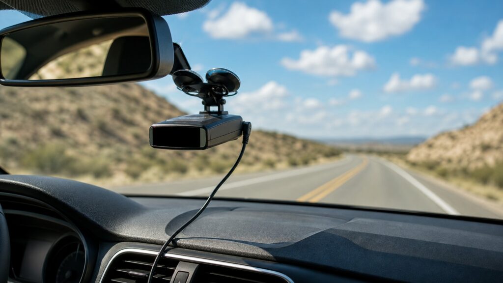
The mechanism moves through collection, frequency selection, pattern analysis, context, prioritization, and human presentation.
Tip: Treat every alert as a classified observation with uncertainty, not as proof of source identity, distance, or legal permission.
These terms describe the receiver stages and the evidence an alert can actually support.
The structure that couples incident radio-frequency energy into the detector's receiver path.
The low-noise amplification, mixing, and filtering stages that translate selected radio energy into signals suitable for analysis.
A defined portion of spectrum within which the detector searches for signals and applies band-specific rules.
A relative estimate of received energy at the detector, shaped by source power, antenna pattern, terrain, reflections, and distance.
A location-based suppression rule used by supported detectors to reduce repeat stationary alerts near stored coordinates.
A light-sensitive path intended to recognize supported pulsed infrared patterns reaching the detector.
Tip: Keep radio, optical, location, and user-setting inputs separate during diagnosis.
Incoming energy must reach the antenna, survive windshield and placement losses, and fall within enabled receiver coverage. Gain helps weak signals, while overload, internal noise, and nearby electronics can obscure or imitate useful observations.
No software can classify energy that the receiver never captures.
The front end converts high-frequency signals into a form that electronics can measure. Filters and sweep or channel strategies decide which frequencies are examined, how quickly, and with what resistance to adjacent interference.
Frequency placement narrows possibilities without naming the emitter.
Digital analysis compares measured behavior with known patterns and rejection rules. Directional designs compare antenna channels; pulse-sensitive designs inspect timing. Classification remains probabilistic because unrelated equipment can resemble the target signals.
A confident label is still a receiver interpretation.
Supported devices may combine GPS position, stored nuisance locations, sensitivity modes, database warnings, and user-selected bands. These layers alter presentation rather than the incoming transmission itself and can suppress something important if misconfigured.
Context should reduce noise without concealing the receiver's limits.
The final system chooses tone, voice, arrows, strength steps, screen detail, mute behavior, and escalation. Presentation must be recognizable with brief attention and must not encourage abrupt, unlawful, or unsafe reactions.
The alert is a cue to reassess driving, not a command or guarantee.
A receiver can report energy that resembles configured criteria without proving who transmitted it, where it is, whether it targets the vehicle, or whether any warning time remains.
It can expose supported radio or optical patterns and organize them by band, strength, direction, location, and priority.
Consistent alert history can help distinguish recurring fixed sources from changing events.
Instant-on radar, narrow laser illumination, terrain, traffic, shielding, disabled bands, and signal geometry can limit or eliminate advance notice.
Safe and lawful speed remains the driver's responsibility at all times.
These myths confuse a passive receiver with a speed meter or certainty engine.
Received level also depends on transmitter power, antenna aim, terrain, traffic, reflections, shielding, and the detector's orientation. A stronger alert often suggests changing geometry, but it cannot be converted into reliable distance by itself.
The label identifies where and how the receiver classified energy. Automatic doors, traffic sensors, other vehicles, interference, or image-frequency effects may create similar observations, so source identity remains uncertain without independent context.
Laser beams are narrow and may illuminate a targeted vehicle area before scattered light reaches a detector. Placement, traffic, weather, and sensor geometry affect reception, so an alert may arrive with little warning.
A stored location can suppress recurring signals near coordinates, but emitters move, frequencies change, positioning drifts, and relevant sources can appear nearby. Review lockouts and use frequency or direction context rather than treating silence as proof.
Tip: Interpret each alert within its sensing geometry and configured limits.
These answers clarify what determines range, false alerts, modes, direction, and response.
Hills, curves, buildings, traffic, source aim, transmitter power, windshield construction, mounting height, antenna orientation, interference, and enabled filters all affect the path. Range is therefore a property of the complete encounter, not one specification.
Many automatic-door and security sensors emit microwave energy in bands a detector may monitor. Location memory, frequency detail, direction, persistence, and appropriate sensitivity modes can reduce nuisance alerts without proving every stationary signal is harmless.
They compare relative energy received by supported antenna channels and estimate whether the signal is ahead, beside, or behind. Reflections and multiple sources can confuse direction, so arrows provide context rather than exact bearing.
Only after confirming current local signal use, travel plans, detector guidance, and legal requirements. Disabling a band can reduce nuisance alerts and scan burden, but it also removes all detection coverage within that configured region.
Maintain control, verify current speed and posted limits, scan traffic and roadway conditions, and avoid abrupt braking or screen interaction. An alert never authorizes speeding and should not replace ordinary observation or judgment.
Radar detectors collect configured microwave energy, sort it by frequency and pattern, add direction or location context, and present a prioritized but uncertain alert. Laser uses a dedicated optical path with tighter geometry.
Their usefulness depends on lawful use, correct placement, enabled coverage, restrained filtering, and calm interpretation. No alert proves source identity, exact range, targeting, or immunity from enforcement.
These explainers apply the signal path to installation geometry, configuration, alert behavior, and safety controls.
Match antenna exposure, windshield, orientation, power, cable routing, heat, controls, and legal conditions to the vehicle.
Define startup, scanning, alerting, muting, lockout, update, failure, and recovery as observable states.
Control legality, mounting, distraction, power, and driver-response hazards.
Choose a retailer
Prices checked regularly. We may earn a commission at no cost to you.