
Windshield Attenuation
Loss of radio or optical energy caused by glass composition, metallic films, coatings, heating elements, tint, or mounting location.
- Loss can vary by frequency
- Clear zones may exist
- Optical and radio paths differ
Radar-detector fit begins with permission: a device that is legal in one place or vehicle class may be prohibited in another. Once lawful use is established, the windshield, mount, antenna orientation, cabin electronics, power behavior, and driver interface determine whether the receiver can detect and present signals as designed.
The apparent installation is small, but its dependencies are not. Metallic coatings can attenuate microwave energy, tint or dots can affect optical sensing, a tilted bracket can change antenna response, and a cable can obstruct controls. Heat, switched outlets, battery drain, vibration, phone links, and false-alert sources must also be tested in the exact vehicle and travel conditions.
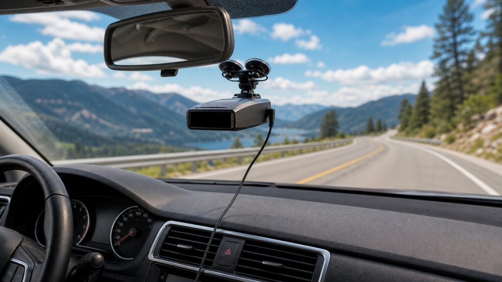
A usable installation requires lawful possession and operation plus clear signal paths, stable geometry, safe power, controlled heat, and understandable alerts.
Tip: Record the intended jurisdictions and vehicle class before choosing a mounting location; legal fit is not something a strong signal can overcome.
These definitions separate installation compatibility from a simple suction-cup check.
Loss of radio or optical energy caused by glass composition, metallic films, coatings, heating elements, tint, or mounting location.
The detector's specified attitude relative to the road, horizon, and vehicle centerline.
The path by which rearward-arriving energy reaches a detector designed to compare or receive from behind.
The space occupied by the detector, bracket, adjustment travel, connector, cable bend, and removal motion.
Compatibility with voltage and outlet behavior during accessory, crank, running, shutdown, sleep, and parking conditions.
A record of alerts or receiver behavior created by the vehicle's own electronics with known outside sources minimized.
Tip: Test the exact detector behind the exact glass whenever coatings or embedded elements are uncertain.
Rules can address possession, use, commercial vehicles, mounting, jamming, and local variations. Check current official sources for every regular route and remove or store equipment as those rules require.
An electrically perfect installation still fails if its use is unlawful.
Coatings, metallic tint, frit areas, heated glass, wipers, pillars, mirrors, and other equipment can alter incoming microwave or laser energy. Compare approved candidate locations rather than assuming all windshield positions are equivalent.
The windshield is an RF and optical component of the installation.
The detector should follow its specified orientation, remain stable over bumps and temperature cycles, and avoid road view, mirrors, controls, occupant contact, and restraint deployment zones. Include the cord and removal motion.
Stable mounting protects both detection behavior and cabin safety.
Use supported adapters and observe accessory switching, cranking, charging, shutdown, and sleep. Direct sunlight can exceed storage or operating limits, while poor grounding or cheap converters may create receiver noise.
Power fit includes silence, sleep, and temperature—not just voltage at startup.
Mount height, speaker path, brightness, control reach, mute method, phone pairing, and display angle affect driver workload. Configure while parked, then log a familiar route without touching the device in motion.
The installed interface should reduce interpretation time, not create another task.
A higher position may improve some signal paths but can violate law, block sightlines, increase heat, reduce control reach, expose cables, or compromise optical sensing through treated glass.
Specified orientation, useful forward and rear exposure, secure retention, and brief alert recognition can coexist.
A tested power and interference baseline makes receiver symptoms easier to isolate.
Disabled coverage, weak processing, instant-on use, narrow laser illumination, or illegal operation cannot be corrected by mount height.
Unknown glass construction may require vehicle or detector guidance.
These myths reduce a multi-boundary fit problem to height, plug shape, or a clean dashboard.
Clear appearance does not reveal metallic coatings, embedded elements, curvature, frit, tint construction, reflections, or laser attenuation. Vehicle documentation and controlled comparison at approved positions provide stronger evidence than visual inspection alone.
Startup does not prove stable operation through cranking, charging changes, shutdown, sleep, heat, or other accessories. The adapter may also create radio noise or parked battery draw that appears only later.
Height can help line of sight, but antenna orientation, treated glass, rear exposure, legal mounting rules, heat, cable routing, control reach, and visual obstruction can outweigh a small geometric advantage.
Vehicle radar, blind-spot systems, traffic sensors, automatic doors, and nearby vehicles can contribute alerts depending on band and filtering. Establish the detector's behavior in the exact vehicle before judging outside encounters.
Tip: Verify the installed vehicle as a system.
These answers help test glass, mounting, power, heat, and interference before relying on the installation.
Check the vehicle manual or glass information for metallic coatings and approved communication zones, consult detector guidance, and compare performance at lawful candidate positions using repeatable sources. Do not infer radio transparency from visual clarity.
Use a lawful location that meets the manufacturer's orientation, signal-path, temperature, retention, sightline, airbag, cable, and control requirements. Test from every regular driver position and account for the complete bracket and removal envelope.
Follow product guidance and verify the actual outlet through accessory, crank, running, shutdown, and sleep states. An always-live outlet may support parking features but can also leave the detector drawing battery power.
Record a quiet-location baseline, then switch chargers, cameras, phones, displays, driver-assistance systems, and adapters one at a time where safely possible. Compare band, direction, persistence, and location before assigning the source.
Confirm legality, secure level mounting, unobstructed sightlines, stable power, controlled heat, usable forward and rear exposure, recognizable alerts, safe mute access, normal sleep behavior, and no new interference across representative roads.
Radar-detector fitment joins legal jurisdiction, glass transmission, antenna geometry, mount retention, cable clearance, power states, heat, interference, and driver workload.
Approve the exact installation only after a parked configuration check and representative road trial. A powered detector on a clear-looking windshield has not yet proven lawful, stable, or usable fit.
These explainers connect physical installation to the signal mechanism, state behavior, and responsible driver response.
Trace antenna capture, band filtering, classification, context, and alert presentation.
Verify startup, scanning, sensitivity, alerts, mute, lockout, and recovery in the installed vehicle.
Audit legal, sightline, cable, distraction, and response risks before road use.
Choose a retailer
Prices checked regularly. We may earn a commission at no cost to you.