
Contact Patch
Area of tread interacting with the road at a given instant.
- Its shape changes with load and pressure
- Rubber force depends on slip and surface
- Water or debris can interrupt contact
A tire and wheel form a pressurized rotating structure between the hub and road. Inflation tension supports the flexible carcass; the tread and compound develop force at a small changing contact patch; the beads seal and anchor the tire to the rim; the wheel carries those forces into the hub and suspension.
Every specification participates. Pressure changes deflection and heat. Load and speed determine stress. Rim width shapes the casing, while diameter and bead profile must match exactly. Offset moves the contact patch relative to bearings and steering axes. Runout or imbalance creates repeating force. A workable assembly therefore requires more than physical fit: size, rating, geometry, fasteners, clearance, sensors, and operating conditions must agree.
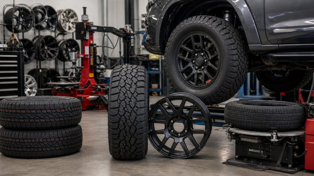
Braking, cornering, acceleration, bumps, and vehicle weight travel through tread rubber, belts, carcass, beads, rim, wheel center, fasteners, and hub. Each layer changes the force before the driver feels it.
Tip: When changing tire or wheel size, record the original load index, speed capability, placard pressure, rim specification, offset, brake clearance, overall diameter, and fastener seat. A diameter match alone leaves most of the system unchecked.
These terms describe the force path and the measurements used to diagnose it.
Area of tread interacting with the road at a given instant.
Cord-reinforced flexible body that contains pressure and carries load between tread and beads.
Precision rim surface supporting and sealing the tire bead.
Distance between wheel centerline and hub mounting face.
Variation in rotating radius that moves the assembly toward and away from the hub center.
Correction of rotating mass distribution across both the circumference and wheel width.
Tip: Use the vehicle placard and manufacturer fitment data for pressure and capacity; sidewall maximums are limits for the tire, not default vehicle settings.
The wheel provides the rigid boundary; the tire's pressurized carcass flexes into a flattened footprint under load. Too little pressure increases deflection and heat, while excessive pressure changes footprint shape, impact response, and available compliance.
The air carries load by tensioning the casing; the rubber is not a solid support block.
Tread blocks deform and rubber shears against microscopic road texture as the tire develops longitudinal and lateral force. Compound temperature, water evacuation, load sensitivity, alignment, pressure, and slip ratio or angle shape the result.
The contact patch is small, dynamic, and already sharing several jobs.
Beads seat against specified rim contours while inflation and fit hold the assembly in place. Rim diameter, width, flange, hump, corrosion, cleanliness, valve, and mounting technique affect seal, casing shape, and bead retention.
A tire that can be stretched onto a wheel is not necessarily a compatible pressure vessel.
The wheel center carries loads from rim to hub. Offset and width position the contact patch, affecting scrub radius, bearing moment, steering feel, fender and suspension clearance, and the path through wheel fasteners.
Changing where the wheel sits changes leverage even if the tire never rubs.
Mass imbalance creates speed-dependent centrifugal force; lateral or radial runout creates geometric motion; casing stiffness variation changes road force under load. Hub rust, wheel damage, seating error, or an out-of-round tire can survive ordinary balancing.
Adding more weight is not a universal cure for vibration.
The assembly works only when pressure, ratings, casing shape, bead geometry, wheel position, hub attachment, and rotating quality remain compatible.
Tire size, service description, construction, load capacity, rim range, pressure guidance, wheel rating, offset, hub, fasteners, valves, sensors, and clearances are verified together.
The mounted assembly seats concentrically, holds pressure, balances within specification, clears through full motion, and produces no abnormal vibration, pull, heat, or interference.
A wheel catalog fit, shared bolt pattern, or matching overall diameter cannot prove load capacity, offset, fastener seating, brake clearance, bearing load, steering geometry, or regulatory suitability.
Stretch, excessive poke, spacers, adapters, mixed ratings, repaired structural damage, or tire-rim combinations outside documented ranges require more than visual clearance and a successful installation.
These myths isolate one familiar measurement from the complete rotating load path.
The sidewall states a tire limit under specified conditions, while the vehicle placard pressure is selected for the original load, axle, handling, ride, and tire configuration. Replacement changes require documented guidance, not automatic use of the maximum.
Bolt pattern does not establish hub bore, offset, width, brake clearance, load rating, fastener seat, thread engagement, or center-cap space. A wheel can bolt on yet misload bearings or contact components.
Balance corrects mass distribution, not bent rims, radial runout, irregular stiffness, shifted belts, eccentric mounting, hub corrosion, loose fasteners, or worn suspension. Vibration diagnosis needs frequency, load, steering, and measured runout evidence.
Width changes contact-patch shape, load distribution, steering effort, water behavior, mass, temperature, rim requirements, and clearance. Available grip still depends on compound, surface, pressure, load sensitivity, alignment, and operating temperature.
Tip: Check the placard, sidewall, rim markings, fitment data, and measured vehicle clearances before accepting a popular shortcut.
These answers cover placard pressure, wheel offset, plus-sizing, torque, and vibration diagnosis.
The placard provides the vehicle maker's cold inflation target for its specified load and tire configuration. The sidewall carries tire identification and maximum-limit information; it is not a universal pressure recommendation for every vehicle.
Offset moves the contact patch relative to steering and suspension axes, changing scrub radius, bearing moment, track width, clearance, kickback, and torque steer potential. Effects depend on the complete front or rear geometry.
Verify load ratings, approved rim width, service description, overall diameter, inflation guidance, offset, hub centering, brake and suspension clearance, fastener seat and engagement, TPMS compatibility, steering travel, payload, and speedometer implications.
Correct staged sequence helps seat the wheel evenly against a clean hub face and produces consistent clamp load. Wrong torque, lubrication, seat shape, damaged threads, or impact-gun use can distort or loosen the joint.
Record speed, steering and load dependence; inspect pressure, wear, damage, and seating; clean hub faces; verify torque; then measure balance, radial and lateral runout, and road-force variation before replacing parts by guesswork.
Tires and wheels work as one pressurized rotating load path: the tire develops road force and carries load through its carcass and beads, while the wheel locates and transfers those forces to the hub.
Safe performance depends on matched size, pressure, ratings, rim geometry, offset, fasteners, clearance, balance, runout, heat, and condition—not merely whether the assembly bolts on and turns.
The next explainers isolate tread architecture and load capacity so their effects can be understood without losing the complete assembly context.
Examine how grooves, blocks, sipes, void ratio, compound support, water evacuation, noise, wear, and surface conditions shape tread behavior.
Learn how load index, pressure, axle weight, speed, heat, replacement sizing, and reserve capacity determine whether a tire can support the vehicle.
Apply tire and wheel damage mechanics when deciding whether a puncture kit, spare, or professional assistance is appropriate.
Choose a retailer
Prices checked regularly. We may earn a commission at no cost to you.