
Controller State
A value, status flag, fault record, or test result reported by an electronic control module.
- Coverage depends on sensors
- Status has context
- Tool support limits access
OBD diagnostic tools read electronic state reported by vehicle controllers. They can reveal codes, status, freeze frame, readiness, and selected live parameters, helping a technician reconstruct what the monitored systems detected. Their evidence is structured, system-specific, and constrained by module coverage and the sensors available to the vehicle.
Dash cameras record light from a limited exterior or cabin view and encode it into time-based video files. That footage may show motion, signals, weather, or impacts the controllers never measured, yet it cannot establish every internal fault. The two evidence streams can support the same investigation, but timestamps, retention, blind spots, and uncertainty must be reconciled before drawing a causal conclusion.
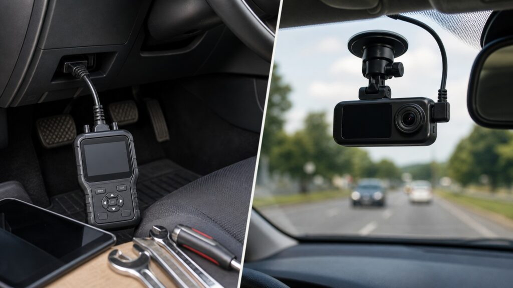
The key difference is the evidence source: module messages describe monitored vehicle conditions, while camera frames preserve visible events within a lens's coverage.
Tip: Ask who observed the fact: a controller, a camera, or the investigator. That answer defines the uncertainty and the next verification step.
These terms identify the separate records that may meet during incident or fault analysis.
A value, status flag, fault record, or test result reported by an electronic control module.
A stored identifier for a monitored condition that met defined fault logic.
A narrow stored set of operating values associated with a supported fault event.
One encoded image representing the lens view at a particular point in the recording timeline.
A file or logical block created as continuous recording is divided for storage and overwrite management.
The process of comparing clocks, offsets, frame timing, and event markers so separate evidence streams refer to the same interval.
Tip: Preserve original files and scan reports before editing, clearing, exporting, or synchronizing anything.
OBD records begin with vehicle sensors, controller logic, and network messages. Video begins with optics, image sensing, exposure, encoding, and storage. Each stream omits facts outside its sensing and retention boundary.
Evidence strength starts with knowing how the record was produced.
A freeze frame may retain selected values near one code-setting event, while live data exists only if logged. A dash camera can provide seconds or minutes around an incident, subject to segment boundaries, overwrite, and file protection.
A shared date stamp does not guarantee identical event timing.
A speed parameter, brake-switch state, voltage record, or communication fault may support one hypothesis. Video may reveal traffic, road surface, lighting, vibration, or an impact. Neither alone automatically proves mechanical cause or responsibility.
Agreement strengthens a reconstruction only when both sources are independently credible.
Code clearing can erase diagnostic context; loop recording can overwrite footage. Export each source using supported methods, retain originals, identify device and software versions, document conversions, and protect sensitive vehicle or location information.
Evidence that cannot be traced to its original state loses explanatory value.
A camera with vehicle-data overlays or an OBD dongle paired to video can place both streams on one screen. Verify module-data accuracy, video coverage, timestamp alignment, storage continuity, and recovery as independent functions.
Convenient synchronization must be demonstrated rather than assumed.
OBD sees selected electronic conditions; a dash camera sees a bounded optical scene. Important mechanical, environmental, human, or network facts may remain outside both records.
Aligned controller data and footage can test whether visible events match reported vehicle state.
Independent records can expose clock errors, sensor limits, or misleading impressions.
Correlation does not by itself prove why a component behaved that way.
Legal conclusions, fault assignment, and safety decisions require appropriate expert and contextual review.
These myths overstate one evidence source or assume automatic synchronization.
A code shows that controller fault logic recognized a condition; it may not carry exact visual timing or physical cause. Align status, freeze frame, logs, footage, and independent inspection before connecting the records.
Footage captures only what enters the lens and survives encoding, exposure, storage, and retention. Internal voltage, network messages, sensor values, actuator commands, and intermittent electrical faults usually require separate diagnostic or physical evidence.
Tool, module, phone, and camera clocks can use different zones, update sources, precision, and drift. Align them with a documented common event and retain the measured offset instead of trusting displayed time alone.
Preview verifies a current image path, not completed encoding, segment closure, file protection, overwrite status, metadata, or retrieval. Open the actual stored clip and adjacent segments before relying on recorded coverage.
Tip: Preserve both originals and keep inference separate from observation.
These answers address evidence selection, preservation, timing, and combined products.
Begin with the OBD path because the question concerns controller state. Save every module's fault status, freeze frame, readiness, and relevant live data, then use footage only if visible conditions help reproduce or contextualize the symptom.
A correctly aimed dash camera may preserve visible lane position and movement within its field of view. Verify the actual file, timing, continuity, and image limitations; OBD data alone normally cannot supply that external scene.
Treat an overlay as a derived value whose source, units, update rate, latency, rounding, and synchronization need verification. Compare it with original diagnostic data and other evidence before making a precise timing or speed claim.
Preserve original and adjacent video segments, metadata, device settings, time offset, full module scan, code status, freeze frame, readiness, and relevant logs. Avoid clearing codes or editing files until the evidence plan is complete.
Independently verify module coverage and values, lens coverage, exposure, segment continuity, overwrite, protection, retrieval, timestamp alignment, startup, shutdown, sleep, and failure indications. Then remove each input to confirm honest degraded behavior.
OBD diagnostic tools differ from dash cameras because one reads structured controller state while the other preserves a time-based optical scene; they observe different facts, retain different windows, and fail in different ways.
Use OBD records for monitored vehicle conditions and video for visible context. Preserve both before clearing or overwriting, align their clocks explicitly, and rely on physical or expert investigation for conclusions neither record can establish.
These related explainers trace controller communication, camera recording, and the operating checks that make each retained record credible.
Trace the diagnostic request, response, decoding, context, and confirmation path.
Follow the complete dash cameras mechanism and its own acceptance evidence.
Check connector, protocol, module, function, power, and workflow compatibility.
Choose a retailer
Prices checked regularly. We may earn a commission at no cost to you.