
Spark-Plug Reach
The threaded length entering the cylinder head between the seat and the end of the shell.
- Too long can contact components
- Too short exposes head threads
- Reach changes spark location
Ignition fitment is the match between combustion-chamber geometry, thermal path, electrical demand, control strategy, sealing, and physical interfaces. A spark plug must use the exact thread, reach, seat, heat range, projection, gap, resistance, terminal, and torque; a coil must match connector, mounting, boot, secondary contact, polarity, dwell, voltage, and control electronics.
A part can screw in or latch yet run too hot, leave threads exposed, strike a piston or valve, shroud the spark, misseal combustion pressure, overload a driver, arc through a short boot, or misfire under load. Resolve VIN, engine code, build date, calibration, and current catalog notes. Compare every interface and follow exact installation procedure rather than treating visual similarity as compatibility.
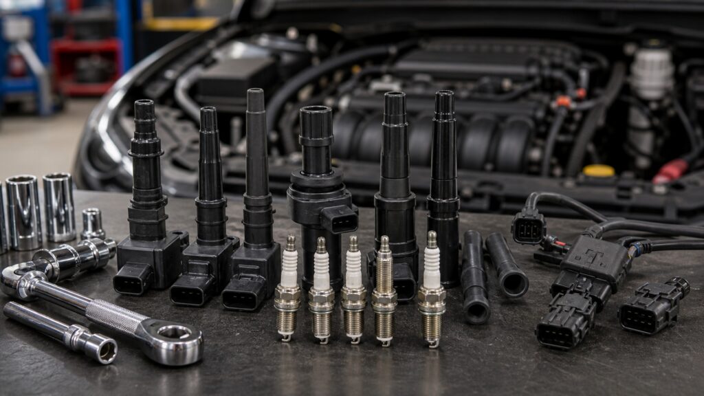
Ignition fitment spans geometry, temperature, insulation, control, and installation force; physical attachment proves only a small part of the match.
Tip: Never use extra washers or thread adapters to make an uncertain spark plug seat; chamber protrusion and heat transfer must remain exactly as designed.
These terms reveal fitment details hidden behind similar hex sizes and connector shapes.
The threaded length entering the cylinder head between the seat and the end of the shell.
The gasketed-flat or tapered interface that seals combustion pressure and establishes installation geometry.
The plug's designed rate of transferring combustion heat from its firing end into the cylinder head.
How far the firing tip extends from the shell toward the combustion chamber and mixture.
The electrical and thermal suitability of a coil for the controller's primary-current charging strategy.
The physical and electrical connection among plug terminal, coil spring, boot, wire end, or threaded cap.
Tip: Keep packaging and removed parts until the engine has passed cold start, hot idle, load, and diagnostic verification.
The firing tip must occupy the intended region without leaving unused threads, striking moving parts, or hiding behind the head. Piston, valve, and chamber clearances vary among closely related engines.
Millimeters of reach can decide sealing, deposit formation, and mechanical survival.
The plug shell transfers heat through its seat and threads. Under-torque can leak and overheat; over-torque can distort the shell, damage threads, or alter gasket behavior. Lubricants can change applied clamp load.
Correct torque is part of the plug's heat range in service.
A wider gap may create a larger initial kernel but requires more breakdown voltage, especially under boost or dense mixture. Excess demand promotes misfire or insulation tracking; too little gap can weaken exposure.
Gap is calibrated with the coil, compression, mixture, emissions strategy, and service interval.
Primary resistance, inductance, current limit, dwell, switching electronics, polarity, suppression, temperature rating, mounting heat path, and secondary design must agree with the control module.
A connector that clicks does not prove the driver and coil share an electrical design.
Coil boots or wires must reach the plug terminal with reliable pressure, seal the well against moisture and oil, and contain secondary voltage. Torn, contaminated, carbon-tracked, or short boots divert energy.
The intended gap must remain the easiest path for every firing pulse.
True ignition fitment aligns chamber position, heat transfer, electrical demand, insulation, controller strategy, and installation procedure.
Current application data confirms engine, build, calibration, plug geometry, heat range, gap, resistance, coil electronics, connector, boot, seals, torque, and any supersession notes.
Installation occurs without force, threads and wells remain clean, contact is positive, no leakage or arcing appears, and misfire data stays normal across cold, hot, idle, and load tests.
Uncertain reach, mixed seat type, improvised washer, unexplained gap, conflicting heat range, damaged thread, wrong connector key, short boot, loose terminal, or unknown dwell compatibility requires resolution first.
A catalog photo, matching hex, shared connector shell, successful threading, or internet cross-reference cannot override exact engine information and documented component specifications.
Fitment myths focus on whether the part enters the hole while ignoring combustion clearance, thermal transfer, and coil-control compatibility.
Thread diameter and pitch do not establish reach, seat, projection, heat range, gap, resistance, clearance, or torque. A wrong plug can leak, foul, pre-ignite, damage head threads, or contact internal components.
Heat range describes how rapidly the plug firing end transfers combustion heat to the head. It does not increase ignition voltage; an unsuitable range can encourage fouling or excessive electrode temperature.
Packaging, transport, catalog errors, application revisions, and delicate electrode designs still require confirmation against exact specifications. Measure only by the approved method and carefully avoid levering against fine-wire center electrodes.
Coils can differ in winding, dwell, current limit, driver integration, polarity, suppression, mounting, boot reach, sealing, insulation, and thermal capacity. Similar housings and keyed connectors do not establish electrical compatibility.
Tip: Require evidence for every hidden interface because the wrong ignition part may damage the engine before an obvious no-start occurs.
These answers cover torque, anti-seize, gap, heat range, and how to resolve conflicting catalogs.
Follow the exact plug and engine instructions. Many plated plugs specify dry installation because lubricant changes friction and clamp load; other applications may differ. Never improvise when torque and thread integrity are safety-critical.
The spark can be recessed, combustion deposits may occupy exposed head threads, heat transfer changes, and later correct plugs may bind. Performance and serviceability suffer even if the engine initially starts.
A too-hot plug may overheat and contribute to pre-ignition, while a too-cold plug may foul under the actual duty cycle. Use the specified range unless an engineered calibration and duty change supports otherwise.
The spring must contact the plug terminal while insulation seals the well and maintains sufficient creepage distance. A short, loose, oil-soaked, or torn boot can arc internally and produce load-dependent misfire.
Check plug torque, coil seating, connectors, harness routing, well seals, start quality, idle, misfire counters, codes, and representative load. Reinspect for arcing, leakage, looseness, or heat effects when symptoms were intermittent.
Ignition-component fitment matters because chamber geometry, heat transfer, gap voltage, coil control, insulation, and installation force are inseparable from reliable combustion.
Resolve the exact application, match every visible and hidden interface, install with documented torque and cleanliness, and verify cold, hot, idle, and load behavior before discarding the evidence.
Related explainers connect ignition energy flow with engine context and replacement-part controls that resolve application splits, supersessions, and post-installation proof.
Follow primary current, coil energy, secondary voltage, gap breakdown, and combustion timing.
Use VIN application, current service data, installation requirements, and verification for replacement-part decisions.
Place ignition within compression, fuel, airflow, cooling, lubrication, exhaust, and electronic controls.
Choose a retailer
Prices checked regularly. We may earn a commission at no cost to you.