
Coil Inductance
The winding property opposing rapid current change and storing magnetic energy as primary current rises.
- It shapes current-ramp slope
- Core condition affects behavior
- Dwell must match inductance
Ignition operating function is a balance between electrical energy, insulation, timing, and combustion. During dwell, primary current rises through an inductive coil and stores magnetic energy. The controller interrupts that current at a selected crank angle, inducing secondary voltage until the plug gap breaks down and a discharge begins.
The first voltage peak establishes an ionized channel; continuing coil energy sustains current long enough to help a flame kernel survive. Cylinder pressure, mixture, turbulence, electrode wear, deposits, temperature, supply voltage, coil resistance, inductance, dwell, and insulation change the required margin. Reliable ignition therefore cannot be judged by peak voltage or plug appearance alone; it must remain stable across cranking, idle, acceleration, boost, heat soak, and emissions control.
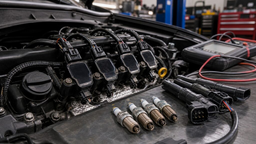
The system succeeds when available coil energy and insulation margin exceed breakdown and flame-initiation demand at the commanded crank angle without excessive thermal stress.
Tip: A wider gap can improve exposure only while coil energy and insulation still provide margin; beyond that boundary, voltage demand rises into misfire or external arcing.
These terms describe the operating curve from coil charging through flame development and control feedback.
The winding property opposing rapid current change and storing magnetic energy as primary current rises.
The region where additional dwell produces little useful magnetic-energy gain but increases heating and electrical stress.
The relationship between secondary and primary winding turns that contributes to voltage transformation during field collapse.
The time current continues through the ionized plug gap after breakdown, supplied by stored coil and circuit energy.
The proximity at which cool metal surfaces can remove enough heat to extinguish a developing flame kernel.
The timing of heat release and cylinder pressure relative to piston motion and crank angle.
Tip: Compare waveforms with exact system specifications and known-good patterns; ignition topologies, probes, polarity, and firing strategies can differ substantially.
Current does not jump instantly through the coil. The ramp depends on supply voltage and winding properties; the controller adjusts charge time while limiting heat as engine speed shortens the available cycle.
Available spark energy begins with a healthy primary charging event.
Interrupting primary current changes magnetic flux rapidly. Secondary voltage follows the load: it climbs toward plug breakdown unless damaged boots, carbon tracks, internal leakage, or test gaps offer an easier route.
The waveform records both coil behavior and the path that accepted the energy.
Once gas ionizes, the voltage across the gap falls while current continues. A tall firing line with inadequate duration, or normal open-air spark with pressure misfire, can reveal insufficient operating margin.
Ignition quality is more than the height of one voltage spike.
Boost and compression increase breakdown voltage; lean or diluted mixtures can challenge flame growth; deposits may leak charge or become hot spots; worn electrodes enlarge the effective gap and expose marginal coils.
The component must operate in the cylinder, not on the workbench.
The controller varies advance with speed, load, temperature, knock, emissions, and fuel assumptions. Misfire monitoring observes uneven crank acceleration, while knock control may retard timing when uncontrolled end-gas reaction appears.
A strong spark at the wrong crank angle remains an operating failure.
Ignition performance combines primary charging, secondary containment, breakdown demand, discharge duration, flame survival, and combustion phasing.
Representative primary-current and secondary-waveform behavior, correct supply and dwell, intact insulation, specified plug geometry, stable misfire data, appropriate timing, and combustion across cold, hot, idle, and load.
Measurements account for cylinder pressure, mixture, boost, temperature, electrode wear, battery voltage, control strategy, and the exact ignition topology.
Peak secondary voltage alone cannot prove spark energy, duration, gap location, correct timing, flame growth, or whether an alternate insulation path discharged first.
Plug color, coil resistance at rest, open-air spark, cleared codes, or smooth idle cannot guarantee margin under compression, heat soak, acceleration, or the original failing condition.
Operating myths confuse demanded voltage with available energy and treat the plug gap as a fixed laboratory load.
Secondary voltage rises only as high as needed to establish the available path, within coil limits. Gap pressure, mixture, insulation, and test setup determine demand; maximum capability is not continuously delivered.
Current eventually approaches saturation, after which added dwell mainly increases heat and driver stress. Controllers tailor dwell to voltage, speed, temperature, and coil design; overriding that strategy can damage components.
Additional gap can expose a larger kernel but raises breakdown demand and insulation stress. Beyond the system's margin, misfire or external arcing increases. Use the exact specified gap and compatible plug design.
Firing voltage is the peak needed to ionize the gap; spark duration describes continuing current after breakdown. Both reflect the circuit and cylinder load, yet neither alone proves correct combustion phasing.
Tip: Judge the complete waveform and combustion response across the engine map instead of maximizing one headline value.
These answers cover saturation, waveform interpretation, gap erosion, boost, multiple sparks, and why operating temperature matters.
Reduced supply slows primary-current buildup and may shorten effective energy before the firing command, especially during cranking. Controllers compensate within limits, but weak connections, starter draw, and coil condition can consume remaining margin.
Erosion rounds electrodes and can enlarge the effective gap, increasing breakdown demand and reducing margin under pressure. Material, combustion temperature, deposits, service interval, polarity, and exact design determine the wear pattern.
With correct tools and interpretation, it can show primary charge, current limiting, firing demand, burn duration, oscillation, alternate arcing, and cylinder differences. Topology and probe placement matter, so compare manufacturer or known-good references.
Higher intake and cylinder pressure increase gas density and plug-gap breakdown demand. A coil, boot, plug, supply, or dwell strategy adequate at idle may then arc externally or fail to sustain combustion under boost.
Certain calibrations can command multiple sparks at selected speeds or conditions to support ignition, but strategy varies. Multiple events do not compensate for wrong plugs, weak supply, damaged insulation, poor mixture, or mechanical faults.
Ignition-component operating function matters because coil energy, voltage containment, gap breakdown, discharge duration, chamber conditions, and spark timing form one changing margin.
Evaluate primary charging and secondary discharge under representative cylinder pressure and temperature, then connect waveforms with timing, misfire, mixture, and mechanical evidence. One voltage number cannot release the system.
Related explainers connect the complete ignition sequence with fitment variables and engine-system inputs that change breakdown demand, flame growth, timing, and diagnostic interpretation.
Follow the ignition sequence from position signal through coil charge, discharge, plug gap, flame kernel, and feedback.
Match reach, heat range, gap, coil electronics, boot insulation, and torque to the exact engine.
Place spark operation within air, fuel, compression, cooling, exhaust, and electronic controls.
Choose a retailer
Prices checked regularly. We may earn a commission at no cost to you.