
Driver Eye Point
The range of eye locations created by seat position, occupant stature, posture, and normal head movement.
- It changes viewing angle
- It changes road obstruction
- Projection alignment depends on it
Driving-display fitment is the match between information and the place where a driver can perceive it safely. A screen may fit a bracket yet block road view, sit outside a useful viewing angle, reflect in glass, interfere with an airbag, overheat in sun, or demand an awkward reach.
The electrical side is equally specific. Speed, warnings, cameras, steering inputs, dimming, and wake states may use vehicle networks or formats that a generic panel cannot interpret. Fitment matters because physical space, optics, data, power, retained functions, controls, and service access must pass together. Diagonal size settles almost none of those boundaries.
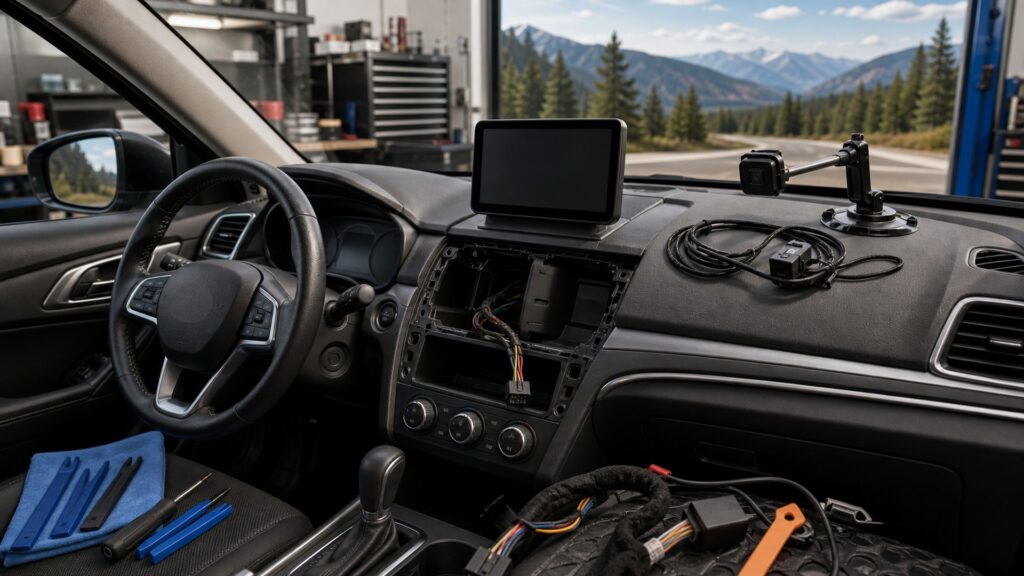
A display belongs in the vehicle only when its image, connections, controls, safety clearances, and maintenance path remain functional across real states.
Tip: Evaluate the complete installation from every regular seating position, then trigger day, night, start, reverse, warning, shutdown, and restart states before accepting fit.
These concepts separate visible packaging from the optical, electrical, data, and human compatibility that makes a display usable.
The range of eye locations created by seat position, occupant stature, posture, and normal head movement.
The complete space occupied by the panel, mount, connectors, adjustment travel, cable bends, and reflected or projected image.
Any installed object or graphic that hides relevant road, mirror, instrument, control, or warning information from the normal eye range.
The match among luminance, contrast, viewing angle, polarization, reflections, windshield properties, and ambient-light response.
Hardware and software translating vehicle-network, camera, phone, or module information into a form the display supports.
A method to inspect, update, disconnect, or remove the display without damaging trim, wiring, safety systems, or calibration.
Tip: A fit claim should name the exact vehicle, display, interfaces, driver geometry, and functions retained.
Fit includes the panel outline, bracket load, articulation, connector depth, cable bend radius, trim movement, vents, controls, mirrors, and occupant motion. A floating or add-on display must remain stable through vibration without becoming a projectile or blocking another function.
A device that occupies the space only while parked has not passed physical fit.
Viewing angle, distance, image scale, glare, reflections, windshield curvature, polarization, and daylight direction determine whether content remains legible. A head-up projection also needs the intended reflective surface and adjustment range to place the virtual image correctly.
Optical fit is measured at the eyes, not at the mounting screw.
The display may need constant or switched power, ground, illumination, reverse state, camera video, vehicle-network messages, phone projection, or sensor input. Voltage, wake logic, protocol, format, and update rate must agree with the exact interfaces.
A connector that fits can still carry the wrong state or signal.
Factory instruments and displays may host telltales, safety messages, climate state, cameras, settings, service information, or steering feedback. Modification must retain required content, its priority, and recognizable behavior rather than merely reproduce entertainment features.
Fit fails when a new screen displaces information the driver still needs.
Touch targets, knobs, steering controls, voice input, and adjustment mechanisms need predictable reach and feedback. Behind the interface, wiring, fasteners, updates, and removal should remain serviceable without entering airbags, pinching harnesses, or forcing finished trim.
An installation is incomplete if ordinary use or later service creates a new hazard.
Application data can identify likely hardware and interfaces, but production variation, options, seating, trim, glass, and existing modifications require final inspection.
Specified brackets, interfaces, formats, dimensions, and supported functions reduce avoidable mismatch before work begins.
A planned acceptance sequence exposes missing inputs or clearances while correction remains practical.
Actual connector population, factory options, windshield behavior, driver geometry, prior repairs, and network state can differ.
No catalog replaces safety-clearance inspection and live function testing.
These myths reduce a multidimensional installation to screen size, bracket fit, or a powered image.
Diagonal measurement omits bezel, bracket, articulation, connector depth, cable bends, vents, controls, road sightlines, reflections, viewing angle, and airbags. The complete display envelope must be measured in its installed and adjusted positions.
Cameras can differ in analog or digital format, resolution, frame timing, aspect, power, connector, trigger, and calibration. A visible plug or adapter does not guarantee compatible video, correct latency, or a supported safety function.
Added luminance cannot remove a blocked road view, extreme viewing angle, reflection geometry, polarization conflict, small text, or excessive nighttime glare. Placement, hierarchy, contrast, and dimming must work together before brightness is increased.
A factory display or receiver may present telltales, chimes, camera views, climate states, settings, or network messages. Removing or obscuring it can change required information even when the new display handles navigation and media well.
Tip: Treat geometry, optics, data, retention, controls, and service as separate fit gates.
These answers address size, windshield mounting, cameras, head-up projection, and the tests required before an installation is accepted.
Record the full panel and mount envelope, connector depth, cable bend, articulation, view distance, road obstruction, control and vent clearance, airbag zones, reach, viewing angle, reflections, and the path needed for secure installation and removal.
No. Laws, vehicle instructions, airbag zones, wiper coverage, camera sensors, tint areas, road sightlines, and driver geometry constrain placement. Verify current local rules and exact vehicle guidance before attaching or routing anything.
An adapter may change a connector without converting voltage, timing, encoding, aspect, resolution, or trigger logic. Confirm the camera and display formats, power, latency, image orientation, and required calibration in every relevant vehicle state.
Projection position, curvature, laminate construction, reflective treatment, tint, dashboard angle, ambient light, and driver eye point affect image alignment and ghosting. Use documented compatibility and test the full seating adjustment range.
Verify secure mounting, road and instrument sightlines, daylight and night readability, controls, warnings, cameras, dimming, startup, cranking, shutdown, network sleep, retained settings, latency, and service access from each regular driver position.
Driving-display fitment matters because physical space, optical delivery, data compatibility, retained information, driver reach, safety clearance, and serviceability are one installed system.
Match the exact vehicle and display, then prove every geometry and operating state from the real eye position. A panel that powers on or fits a bracket can still fail its most important visual and vehicle interfaces.
These explainers show what each connection must carry, why its operating contract matters, and how placement and interaction create separate safety boundaries.
Trace the information, priority, rendering, optics, and feedback paths that every fitted interface must support.
Define sources, vehicle states, outputs, limits, and fallback behavior for each display capability.
Audit obstruction, glance demand, brightness, alerts, controls, mounting, and failure response after fitment.
Choose a retailer
Prices checked regularly. We may earn a commission at no cost to you.